ContentsFigures & Tables
Against the backdrop of the transformation and upgrading of the automotive industry, proton exchange membrane fuel cells (PEMFCs) have attracted widespread attention due to their broad application prospects [1–5]. PEMFCs possess prominent characteristics such as high energy efficiency, environmental friendliness, and rapid cold-start capability, which enable them to demonstrate great potential in the field of automotive power technology. Therefore, PEMFCs are regarded as one of the important technical approaches to achieve the clean transformation of vehicle power systems [6–10]. In a fuel cell vehicle system characterized by high coupling and precise regulation, the performance of the subsystems responsible for hydrogen supply [11], anode pressure regulation, and gas humidification directly determines the dynamic response and output characteristics of the entire system [12, 13].
To ensure stable and uniform reactions on the anode side of a PEMFC, an excessive amount of hydrogen is typically supplied [14], while the unreacted residual hydrogen is usually vented directly to the atmosphere. This not only wastes hydrogen but also poses safety risks [15]. To mitigate these issues, fuel cell systems commonly operate in dead-end and recirculation modes [16]. In dead-end mode, the absence of forced convection and the surplus hydrogen supply can lead to flooding and starvation within the fuel cell stack. Conversely, in the recirculation mode, the anode's unused hydrogen is redirected back into the fuel cell through hydrogen recirculation equipment, allowing it to re-enter the reaction process [17]. This method can effectively suppress the risk of anode crossover and ensure the stable supply of hydrogen in the reaction zone. For this reason, it has become a widely applied technical strategy in proton exchange membrane fuel cell systems [18, 19]. At present, the mainstream hydrogen recirculation equipment is mainly designed based on the ejector and the hydrogen circulation pump [20]. However, the use of hydrogen circulation pumps can cause additional parasitic power consumption and reduce system efficiency. Meanwhile, these pumps entail high control and maintenance costs, and their operational noise and vibration can also adversely affect the fuel cell system [21]. In contrast, ejectors have garnered significant attention due to the advantages of small size, zero energy consumption, reliable operation, and low cost [22]. In view of this, conducting research on anode subsystems based on ejectors is one of the key driving forces for promoting the performance improvement of fuel cell vehicles and realizing their large-scale commercial application.
On the anode side of the fuel cell, the supply pressure of hydrogen is unstable, which will directly affect our power generation efficiency and how long this stack can last. Therefore, using advanced control methods to manage hydrogen supply is the key factor to ensure the stable operation of the whole system [23]. At present, a lot of research in academic circles has focused on various advanced control methods, and its goal is to make the control of the hydrogen supply system more accurate and more resistant to interference. For example, Zhang et al. [24] proposed a purging-based distributed model prediction method, validated its excellent performance during purging, and proposed a new model switching strategy. He et al. [25] developed an observer-based state feedback controller (SFB), which can be used to observe the two-phase phenomena occurring in the gas diffusion layer (GDL) more effectively, and compared it with proportional integral control and static feedforward control to verify its excellent tracking and immunity performance. Wang et al. [26] developed a prescribed-performance multiple-input–multiple-output (MIMO) neural network controller for PEMFC hydrogen management, enabling precise regulation of anode pressure and hydrogen excess ratio without prior knowledge of the model and relaxing the initial error constraint. To ensure stable anode pressure across the entire 70 kW power range of the fuel cell, Chen et al. [27] developed a novel hydrogen supply system utilizing dual ejectors and implemented a corresponding control strategy. Ye et al. [28] proposed an enhanced common rail injection system, featuring an integrated Mamdani fuzzy logic controller for dynamic anode pressure regulation. Yuan et al. [29] developed a fuzzy-logic-based proportional-integral (PI) controller (FLPIF) that incorporates feedforward compensation for variations in load current and purge-related disturbances, thereby greatly enhancing the transient response of hydrogen pressure. Wei et al. [30] introduced an adaptive fuzzy second-order active disturbance rejection control (ADRC) designed for oxygen excess ratio (OER) tracking in a 100-kW automotive fuel cell system, which improves power generation efficiency and dynamic performance. Hong et al. [31] developed a multivariable nonlinear feedback controller for a dynamic control-oriented model of fuel cell systems incorporating anode recirculation, with the objective of ensuring sufficient hydrogen supply and maintaining optimum hydrogen levels in the anode. Quan et al. [32] introduced a MIMO model predictive control strategy based on the pseudo-reference concept, which was integrated with feedback linearization technology to stabilize the anode pressure and hydrogen stoichiometry of the system. When they used the simulation scenario of the New European Driving Cycle to test, the average overshoot of anode pressure and hydrogen stoichiometric ratio were reduced by 47.45% and 77.34%, respectively, compared with those of the conventional model predictive control (MPC). Finally, the employment of a Hardware-in-the-Loop (HIL) testbed served to experimentally confirm the real-time operational efficacy of the proposed control strategy. Liu et al. [33] proposed a novel co-control framework that integrates twin delayed deep deterministic policy gradient (TD3)-based deep reinforcement learning (DRL) with a Long Short-Term Memory (LSTM) risk prediction model for optimal purge management in PEMFC systems. Ge et al. [34] proposed an improved hydrogen supply system based on the Multi-strategy Improved Sparrow Search Algorithm (MISSA), which optimizes the emission performance of the hydrogen supply system for fuel cells.
This work introduces a new backstepping sliding mode controller, which is specially designed to manage the fuel cell hydrogen supply system based on an ejector. First, an ejector-based hydrogen supply system for a 50 kW fuel cell is developed. Then, a backstepping sliding mode control scheme utilizing the purge signal is formulated. Simulation outcomes ultimately demonstrate that the proposed radial basis function (RBF)-based backstepping sliding mode controller has good performance in resisting sudden changes in the external load current and the interference of the purge signal. This study provides a novel solution for pressure regulation in PEMFC anode gas recirculation systems by integrating an RBF neural network to compensate for unmodeled gas flow disturbances, particularly those induced by periodic purging. The proposed approach addresses key challenges in gas dynamics management, including ejector-driven recirculation and transient pressure variations during purging. The structure of this paper is as follows. Section 2 describes the establishment of a 50 kW fuel cell anode hydrogen supply model based on an ejector; in Section 3, a backstepping sliding mode control scheme incorporating a RBF neural network is developed; while Section 4 presents a comparative simulation analysis between this controller and a conventional proportional‑integral‑derivative (PID) controller, and provides the concluding remarks.
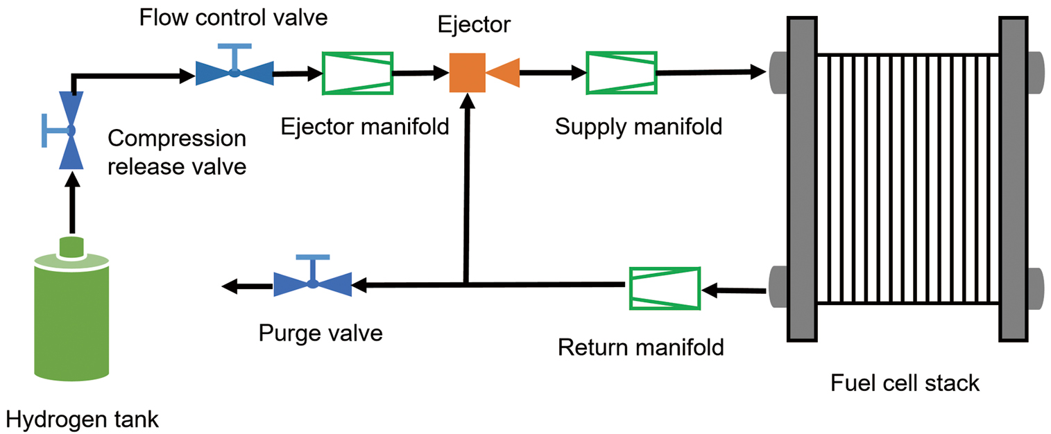
Figure 1 depicts the single-ejector-based anode hydrogen supply system for a fuel cell. The system comprises a high-pressure hydrogen tank with a pressure-reducing valve, a proportional valve, a purge valve, three essential manifolds (ejector, supply, and return), an ejector, and an anode flow path. The three manifolds direct hydrogen gas to various flow channels within the fuel cell. When modeling the manifolds in the system to capture the transient behavior of the fluid, the internal volume is experimentally considered as the control volume. In this paper, the model of the control system is simplified by omitting the modeling of the high-pressure hydrogen tank with its pressure regulator [35].
Several key assumptions are adopted for the development of the component model:
Assumption (1): the behavior of gases in all control volumes follows the ideal gas law;
Assumption (2): pressure losses through the interconnecting pipes are considered negligible;
Assumption (3): an isothermal condition is maintained across all manifolds;
Assumption (4): high humidity in stacks and pipes;
Assumption (5): no gas crosses the membrane, and no gas leaks into the fuel cell.
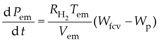
This model of the fuel cell hydrogen supply system primarily consists of three essential manifolds (ejector, supply, and return). The proportional valve is linked to the ejector's primary inlet via the ejector manifold. Since the fluid flowing through the ejector manifold is pure hydrogen, the model only needs to account for the dynamic changes in hydrogen pressure. The transient behavior of the hydrogen pressure inside the control volume is governed by the following Equation (1):(1)where Pem denotes the hydrogen pressure within the injector manifold, a value equivalent to the pressure at the injector's primary inlet. Variables Wfcv and Wp correspond to the mass flow rates across the proportional valve and the main inlet of the injector, respectively. Furthermore, , Tem, and Vem correspond to the hydrogen gas constant, the gas temperature, and the volume of the injector manifold, in sequence.
The supply manifold delivers hydrogen to the fuel cell, with gas entering the pipeline from both the proportional valve and the ejector. According to Assumption (1), the internal pressure and flow rate of the supply manifold are considered constant. The fuel cell anode's flow path is coupled with the ejector's suction port via the return manifold. Utilizing the pressure energy of the primary high-pressure flow, the ejector recirculates unconsumed hydrogen from the anode outlet back to the supply manifold. Under stable flow conditions within the return manifold, the resulting mass flow rate can be determined from the pressure differential across its two ends. The corresponding dynamic model is given by Equation (2) [36]:(2)In this formulation, Wrm refers to the mass flow rate of the gas flowing through the return manifold. Prm, in corresponds to the return manifold inlet pressure. This pressure is identical to that at the anode outlet of the fuel cell stack, denoted as Pan. Prm, out signifies the return manifold's outlet pressure under the condition of a closed purge valve, which is equivalent to the ejector's secondary flow pressure Ps. Finally, krm defines the scaling coefficient for the return manifold.
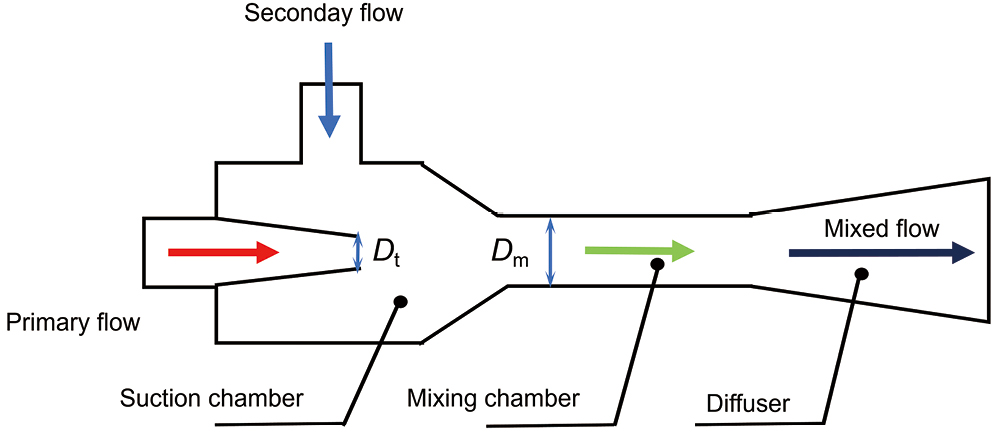
Ejectors are prevalent recirculation devices in fuel cell systems, valued for their cost-effectiveness, structural simplicity, zero parasitic power load, and quiet operation [37]. Currently, the design method commonly used is based on the Sokolov ejector. The ejector's modeling and analysis are conducted according to the principles of conservation of energy, mass, and momentum [38]. A schematic diagram depicting the ejector's configuration is presented in Figure 2.
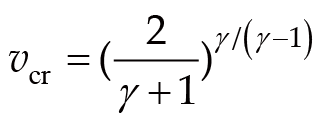
Within the fuel cell's hydrogen supply system, the working fluid of the ejector is pure hydrogen originated from the high-pressure hydrogen storage tank and regulated by the pressure-reducing valve. The potential energy inherent in this high-pressure flow is harnessed to entrain and recirculate the unreacted hydrogen, along with its water vapor content, from the anode exit. These two fluids further re-energize the fuel cell stack by mixing in the injector and discharging through the diffusion chamber. Based on the available studies, ejector functionality can be categorized into three distinct regimes: backflow, subcritical, and critical operation [39]. The specific regime in which an ejector operates is governed by the relative values of its back pressure and the critical pressure ratio across various working conditions. The ejector's back pressure, measured at its outlet, is identical to the hydrogen pressure delivered to the fuel cell stack. The critical pressure ratio is defined by Equation (3):(3)where γ denotes the ratio of specific heats for the gas.
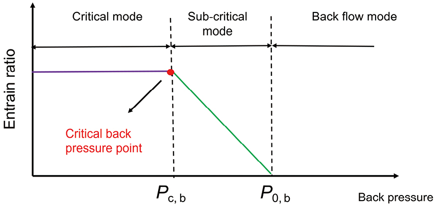
As shown in Figure 3, when the ejector's operating back pressure is less than its critical pressure ratio (Pc, b), the ejector functions in critical mode. Operation transitions to the subcritical regime once the back pressure surpasses the critical pressure ratio. From the literature, in subcritical mode, the ejector's performance declines rapidly, which should be avoided whenever possible. In back flow mode, where the operating back pressure exceeds a certain threshold (P0, b), the ejector cannot properly inject the circulating fluid. Therefore, the back flow mode is excluded from the present ejector model to facilitate stable numerical simulation.
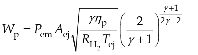
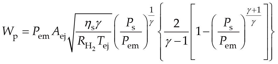
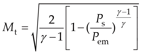
When operating in the critical mode, the ejector's nozzle throat attains a Mach amount of unity. The primary mass flow rate can then be derived using isentropic flow relations and energy conservation. This calculation is performed as Equation (4) [40]:(4)where Aej represents the nozzle throat area, ƞp denotes the flow isentropic coefficient, and Tej represents the fluid temperature in the ejector. For the subcritical mode, the primary flow's mass flow rate and Mach number at the nozzle throat are calculated as Equations (5, 6) [40]:(5)(6)where ƞs denotes the isentropic coefficient for the secondary flow.
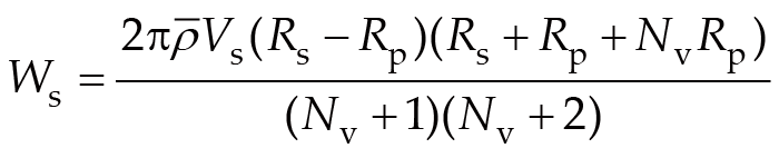
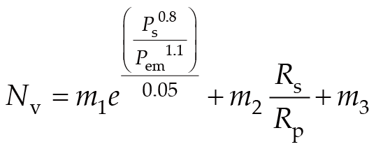
The secondary flow's mass flow rate is obtained by integrating across the annular region from the tube wall to the primary flow boundary. In the critical mode of the ejector, this secondary flow rate is given by Equations (7, 8) [40, 41]:(7)(8)where Rp and Rs represent the flow radii of the primary flow and the secondary flow, respectively; ρ represents the average density of the secondary flow fluid; Vs represents the speed of the secondary flow; m1, m2, and m3 are the fitting parameters, respectively; and Nv is the exponent of the velocity function.
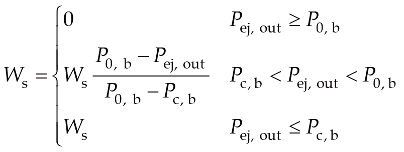
In subcritical mode, the ejector ratio decreases linearly as the back pressure increases. The actual mass flow rate of the secondary fluid in different modes can be calculated using the following linear interpolation method:(9)where Pej, out represents the working back pressure of the ejector.
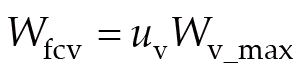
Precise regulation of the hydrogen supply flow in the fuel cell system is accomplished through modulation of the proportional valve. The control signal exhibits a roughly linear relationship with the proportional valve flow; this allows the mass flow rate to be regulated by varying the open cross-sectional area for gas flow. Specifically, this relationship is expressed as Equation (10) [42] :(10)where uv denotes the control signal for the proportional valve opening, normalized between 0 and 1, while Wv_max represents the maximum attainable mass flow rate under fully open valve conditions.
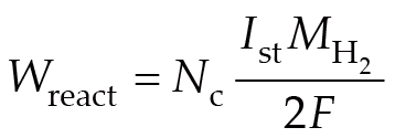
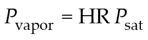
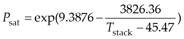
This paper focuses exclusively on studying the fuel cell anode hydrogen supply system, thus necessitating the establishment of a model solely for the anode side of the fuel cell. Treating the entire anode channel as a control volume and disregarding the influence of nitrogen and water vapor permeation from the cathode, the dynamic response of pressure within the anode channel can be formulated as follows:(11)where Pan represents the anode pressure, Van represents the volume of the anode flow channel, Tan signifies the temperature of the gas within the anode, Win represents the hydrogen mass flow rate entering the fuel cell anode, and the variable Wout defines the outgoing hydrogen mass flow rate from the anode channel. Wreact is the mass flow rate of hydrogen consumed in the stack, calculated by Equation (12) [43, 44]:(12)where Nc denotes the number of single cells in the stack, Ist corresponds to the fuel cell's load current, is the molar mass of hydrogen, and F is the Faraday constant. The water vapor partial pressure (Pvapor) within the anode flow path is determined by the fuel cell's relative humidity (HR) and the water vapor saturation pressure (Psat). The saturation pressure of water vapor is a function of the stack temperature, calculated as Equations (13, 14) [45]:(13)(14)
The fluid mass flow rate through the purge valve is governed by Equation (15):(15)where Ppu, in represents the inlet pressure of the purge valve, which is equal to the pipe pressure on the outlet side of the fuel cell stack. Ppu, out represents the outlet pressure of the purge valve, which equals atmospheric pressure Patm. The flow coefficient of the purge valve is designated as Kv, while αp indicates its on-off status, with 1 and 0 corresponding to open and closed states, respectively. Tpv corresponds to the temperature of the fluid within the purge pipe, and ρN represents the fluid density under standard conditions.
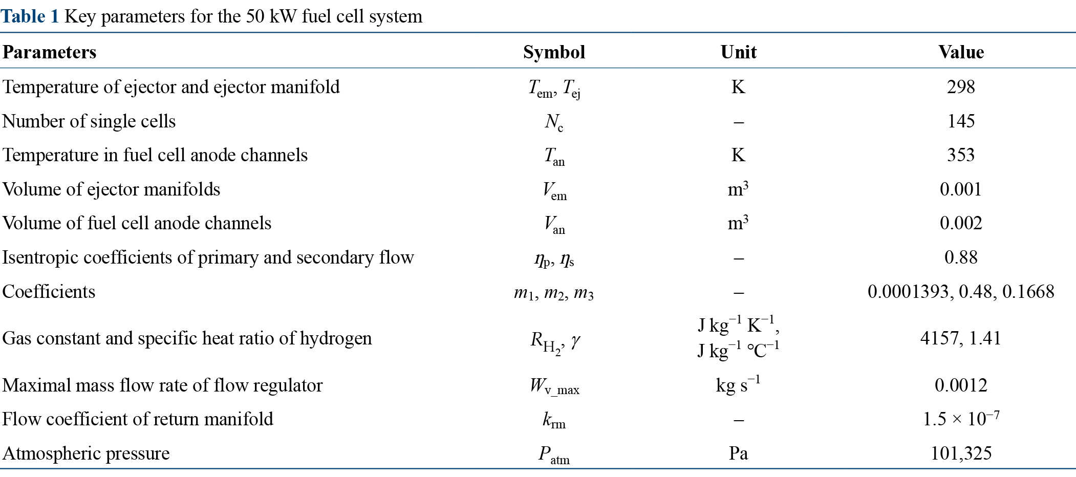
The key parameters for the 50 kW fuel cell anode system are summarized in Table 1.
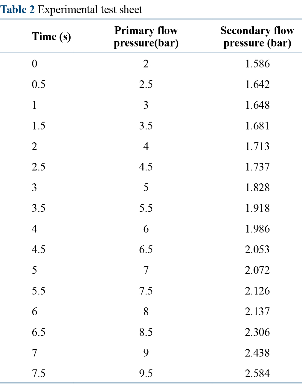
The ejector-based anode pressure regulation system was validated through experiments performed on a dedicated fuel cell test stand. During testing, air was employed as a safe substitute for hydrogen to replicate the reactant supply dynamics. Model performance was assessed over the fuel cell stack's entire designated power range through a linear ramp-up of the air pressure supplied to the ejector from 200 to 950 kPa, as shown in Figure 4A. Throughout this procedure, the pressure at sixteen locations along the secondary flow path was measured; the resulting data are compiled in Table 2.
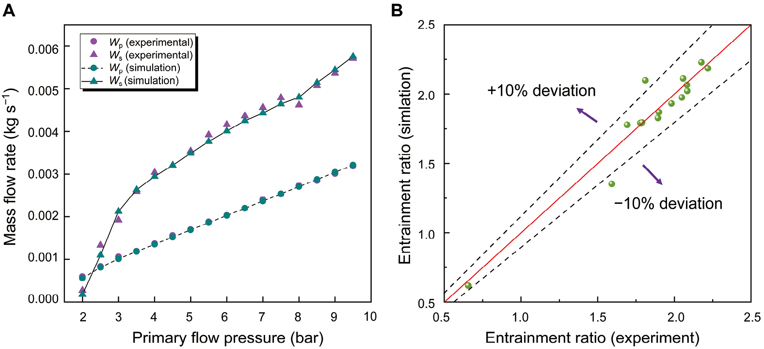
Using the appropriate thermodynamic properties for air, the model's predictions were evaluated against the sixteen experimental measurements, as shown in Figure 4B. The primary mass flow rate exhibited a linear increase in response to the rising power demand from the fuel cell. The flow characteristics of both the primary and secondary flows are consistent with the trends in Reference [41], with the error range controlled within 10%, thereby validating the accuracy of the established model.
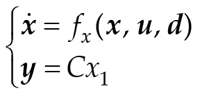
The mathematical formula reflecting the relationship between flow and pressure components is brought into the derivation, resulting in a state-space representation of the controlled hydrogen supply system, expressed as Equation (16):(16)where the state vector x = [Pan, Pem]T comprises the fuel cell anode pressure and the ejector primary flow pressure. The output variable y corresponds to the fuel cell anode pressure, and the interference d accounts for the impact of load current variations on the system dynamics, while the control input u defines the opening degree of the proportional valve.
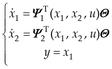
To facilitate the subsequent controller design, take use of the form of a column vector to define:(17)where , Ψ1 = [x2 + d 0 0]T, and Ψ2 = [0 x2u]T.
The integration of backstepping control with sliding mode control effectively addresses the challenges posed by complex nonlinear characteristics and various external disturbances in the hydrogen supply system [46]. This control strategy enhances the system's stability and robustness, meeting the requirements for real-time and dynamic performance. The controller design process is outlined as follows:
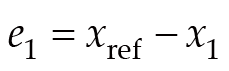
First, define the anode pressure error as:(18)
The time derivative of the state vector e1 is therefore expressed as:(19)
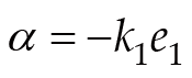
Define the stable variable:(20)where k1 represents a positive constant.
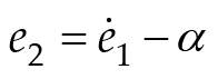
Define an auxiliary error variable for tracking purposes:(21)
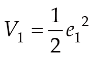
The first Lyapunov function is chosen as:(22)
Differentiating V1 yields:(23)
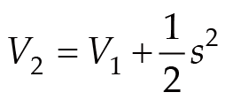
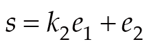
A second augmented Lyapunov function is defined as:(24)where s is the sliding surface given by:(25)where k2 is also a positive constant. Using Equations (24, 25), the derivative of V2 can be derived as Equation (26):(26)
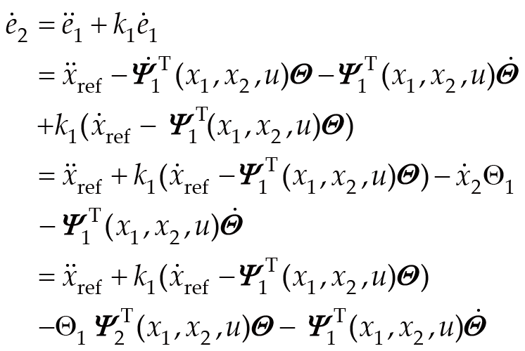
The derivative of with respect to time is expressed as:(27)where represents the first component of the matrix . For the fuel cell hydrogen supply system, an exponential reaching law for the sliding mode surface is formulated as follows:(28)where h and β are positive constants.
It should be noted that the first-order sliding mode controller adopted in this study has an inherent chattering phenomenon caused by the discontinuous switching function. The chattering is mainly attributed to the high-frequency switching behavior around the sliding surface, which may lead to oscillations in the control input. In practical PEMFC hydrogen recirculation systems, excessive chattering may influence the actuator response and pressure regulation performance.
However, the main objective of this study is to enhance the robustness of hydrogen pressure regulation under nonlinear disturbances and parameter uncertainties. Therefore, the sliding mode term is retained to guarantee system stability and disturbance rejection capability.
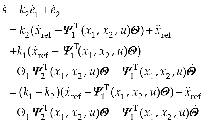
Accordingly, the dynamics governing the sliding manifold are formulated as:(29)
The sliding mode is established if , whereby the control input u is derived as:(30)
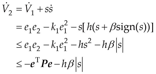
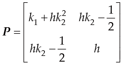
The stability analysis for the backstepping sliding mode control is elaborated as follows. By reintroducing the derived control rate into Equation (27), the derivative of the Lyapunov function is defined as:(31)where e = [e1e2]T and P is a symmetric matrix having the structure:(32)
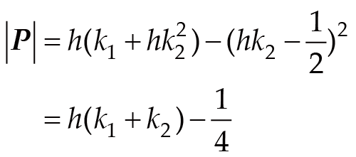
Consequently, for to be negative definite, P must be a positive definite symmetric matrix, which requires its determinant |P| to be positive:(33)
Through proper selection of parameters k1, k2, and h, a positive determinant of P (|P| > 0) can be ensured.
At this point, specify the term that follows:(34)
Through the integration of Equation (33), it can be derived that:(35)
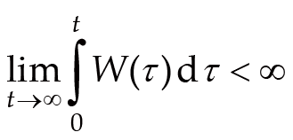
Due to the fact that V2 (e1(0), e2(0)) is bounded, V2 (e1(t), e2(t)) is non-increasing and bounded, so:(36)
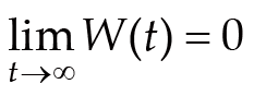
Since is additionally bounded, it follows that W(t) is uniformly continuous. In light of Barbalat's lemma, the corresponding conclusion can be derived:(37)
Hence, the backstepping-based sliding mode controller exhibits asymptotic stability. Accordingly, both e1 and e2 tend to converge to the zero value. During the calculation of the backstepping sliding mode controller, it becomes evident that the design of the final controller effectively utilizes each state variable of the fuel cell hydrogen supply system. As a result, the system exhibits excellent control characteristics.
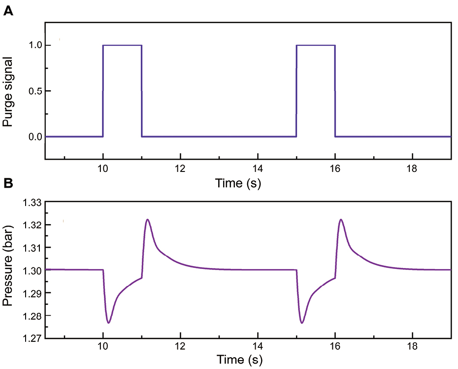
In order to remove the water vapor generated inside the stack, prevent it from piling up on the electrode surface, the phenomenon of "flooding", and ensure the high-performance operation of the fuel cell system, the fuel cell needs to be periodically purged, and the anode pressure will fluctuate during the purging process, as shown in Figure 5. When the purge signal steps from 0 to 1, it means that the purge valve is open at this time, and part of the gas flow will be discharged to the outside, and the gas flow participating in the circulation will also decrease accordingly, so the anode pressure will decrease accordingly. When the purge valve is closed, the system returns to the initial normal operating state, but due to the lagging dynamic response characteristic of the proportional valve at the front end, hydrogen will still be over-supplied to the stack. At this time, the reaction rate of hydrogen inside the stack does not change, resulting in a temporary increase in anode pressure.
In cases where the fuel cell system operates under medium to high load conditions, the anode hydrogen supply pressure typically surpasses 170 kPa, and during the purge process, the anode-cathode pressure difference surpasses 20 kPa. A fuel cell's proton exchange membrane is generally capable of withstanding the threshold that the anode-cathode pressure difference should not exceed 40 kPa, so it is necessary to consider the influence of the purge process and further optimize the controller.
During system purging, the flow characteristics of certain components change, impacting the overall system state and introducing unknown disturbances. The original backstepping sliding mode controller (BSMC) is not effective in managing the system under these conditions. To address this issue, Radial Basis Function Neural Network (RBFNN) is employed to estimate the nonlinear disturbance caused by the purge-induced gas flow disturbance to the hydrogen supply system of the fuel cell.
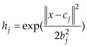
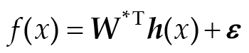
The RBFNN is composed of three layers, namely an input layer, a hidden layer and an output layer, while it demonstrates superior generalization capability [47, 48]. Theoretically, an RBF neural network can approximate any nonlinear function within a compact set to an arbitrary level of precision. It also demonstrates strong approximation capabilities and rapid convergence speed. The uncertain effect f(x) caused by purge-induced gas flow disturbance can be expressed as Equations (38, 39) [49]:(38)(39)where j represents the j-th node situated in the hidden layer, x denotes the input variable of the RBF neural network, and cj stands for the central point coordinate of the Gaussian basis function corresponding to the j-th hidden layer neuron. bj signifies the width parameter of the Gaussian basis function associated with the hidden layer neuron. W* represents the ideal weighting matrix for the RBF neural network; h(x) denotes the output of the hidden layer; ε stands for the approximation deviation of the RBF neural network.
In this work, the RBF neural network is introduced to approximate the unknown nonlinear disturbances and compensate for modeling uncertainties in the hydrogen subsystem. It should be clarified that the RBF neural network is not directly designed for eliminating the chattering phenomenon of the sliding mode controller. The switching term in sliding mode control (SMC) is still necessary to guarantee robustness against uncertainties. By improving disturbance estimation accuracy, the RBF compensation can reduce the influence of unknown dynamics on the control system, which helps improve the overall control performance.
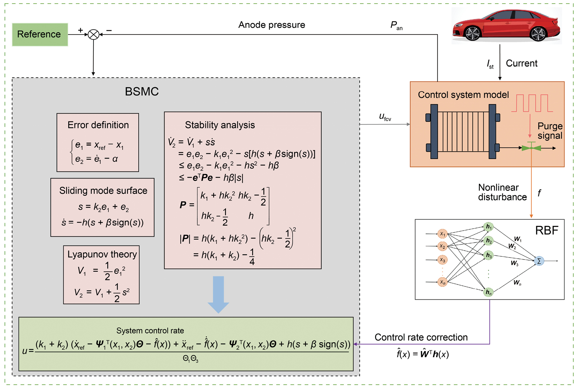
The dynamic equation of ground anode pressure of the fuel cell hydrogen supply system can be rewritten as:(40)where , represents the estimated weighting matrix for the RBF neural network. According to the above derivation, the new neural network backstepping sliding mode control (NNBSMC) rate can be obtained as shown in Figure 6 (Equation (41)):(41)
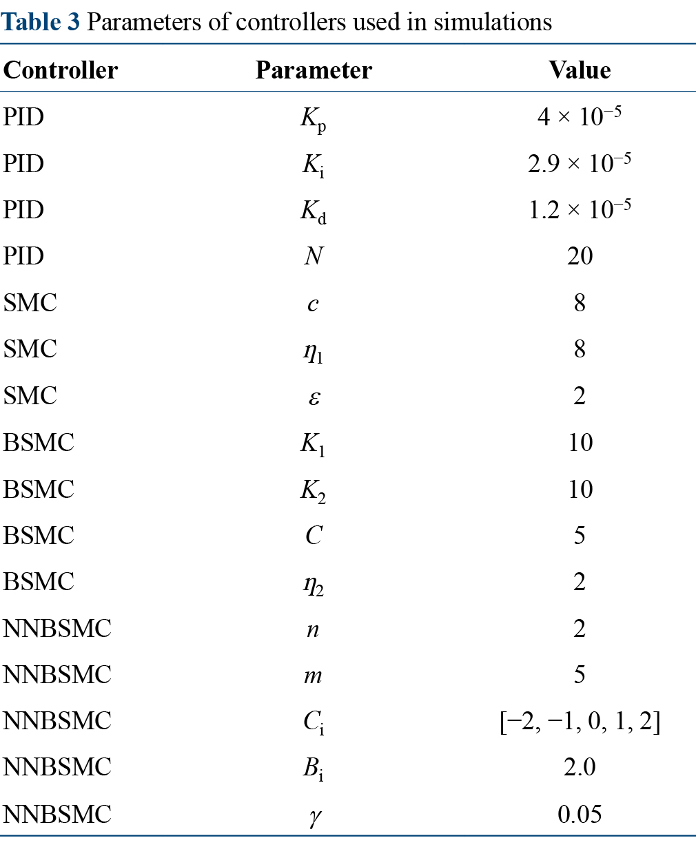
Therefore, all the parameters of the relevant controllers were summarized, as shown in Table 3.
Firstly, the control effect is compared in the scenario without a purge signal. The load current step condition that fluctuates within the appropriate current range is input to the system, which is from 250 to 320 A as shown in Figure 7A, and the simulation effect of the three control algorithms of the fuel cell hydrogen supply system under the ideal state is obtained. Figure 7B shows the tracking curve of the anode pressure of the fuel cell system under the control of PID, SMC, and BSMC controllers. Compared with the current step condition, it can be seen that when the load current rises, the hydrogen consumption of the stack increases, and the anode pressure will show a short downward trend due to the hysteresis of the system response. Similarly, when the load current drops, the hydrogen consumption of the stack decreases, and the anode pressure rises briefly. When the current is stable, the three controllers can stabilize the anode pressure well. It can be observed from Figure 7C that compared with the PID controller, the BSMC controller, and the SMC controller both show faster response speed, can reach the control target in a shorter time, and have no overshoot phenomenon, and the performance is significantly better than the PID controller. At the same time, it can be seen from Figure 7D, E that in the process of upward or downward step of the external load current, the BSMC controller has the optimal pressure fluctuation suppression effect, the adjustment time of the system is shorter, and the anode pressure can be restored to the set target value more quickly.
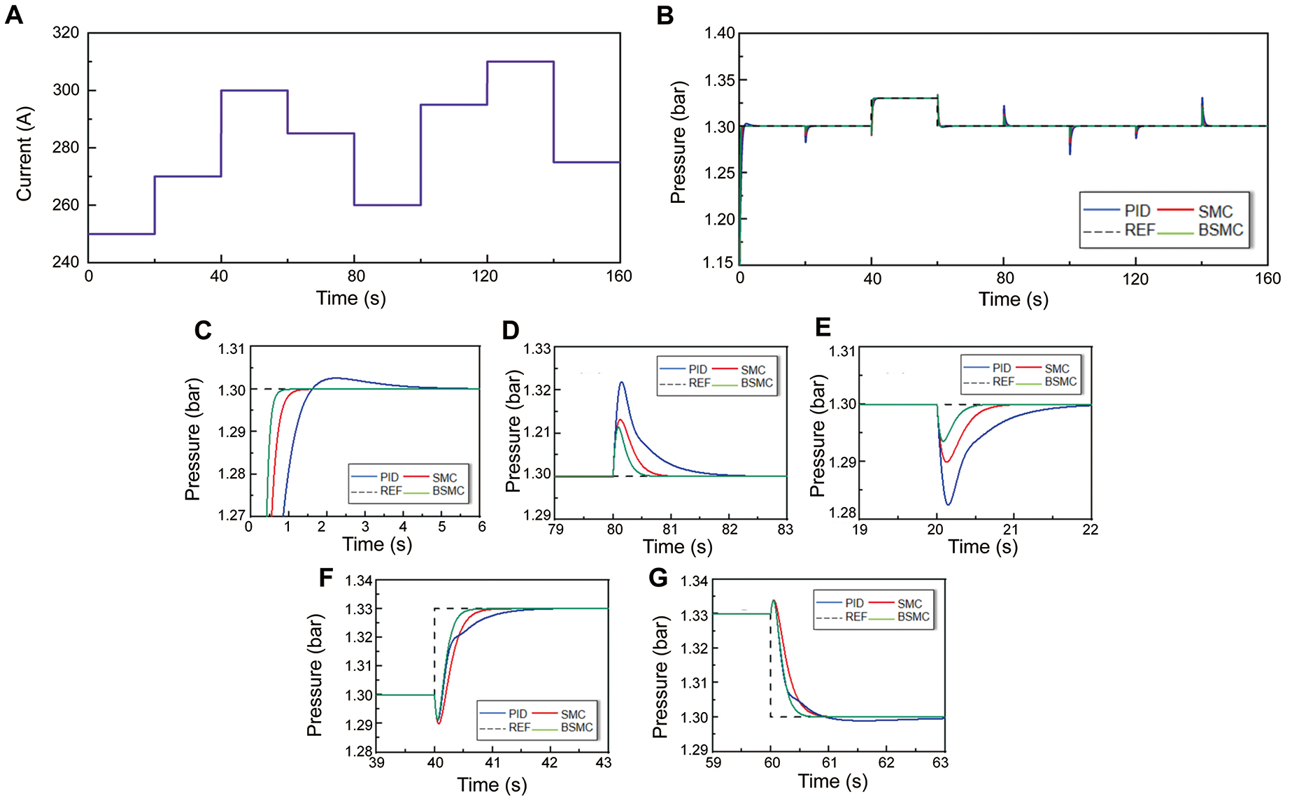
There is a certain relationship between the hydrogen supply pressure and the load current of the fuel cell anode. When the load current demand increases, the fuel cell needs more hydrogen flow to support the electrochemical reaction. Increasing the anode pressure can increase the diffusion rate of hydrogen and ensure that enough hydrogen can be quickly transferred to the electrode surface. Meanwhile, high load current will lead to increased polarization loss of the fuel cell electrode. By increasing the pressure of the anode gas, the polarization loss of the electrode can be reduced, and the rate of electrochemical reaction can be improved. Conversely, when the load current demand is reduced, the anode pressure can also be appropriately reduced to improve the hydrogen utilization rate. Therefore, in order to better simulate the actual working state of hydrogen supply by the fuel cell anode, the load current increases upward and the theoretical reference pressure increases at the 40 s of the input step current condition, while the load current decreases downward at the 60 s, at which time the theoretical reference pressure is also reduced. Thus, the control effects of the three controllers in Figure 7F, G are obtained. Among them, the control effect of the BSMC controller is obviously better than that of the SMC and PID controllers.
In an effort to further verify the control performance of the designed NNBSMC controller, a periodic purge signal is added under the above step current condition, and a purge signal is carried out every 15 s with a purge time of 1 s. The load current step condition that fluctuates within the appropriate current range is input to the system, which is from 250 to 320 A as shown in Figure 8A. The purging signal is presented in Figure 8B. The control performance of PID, BSMC, and NNBSMC controllers is compared under the working condition.
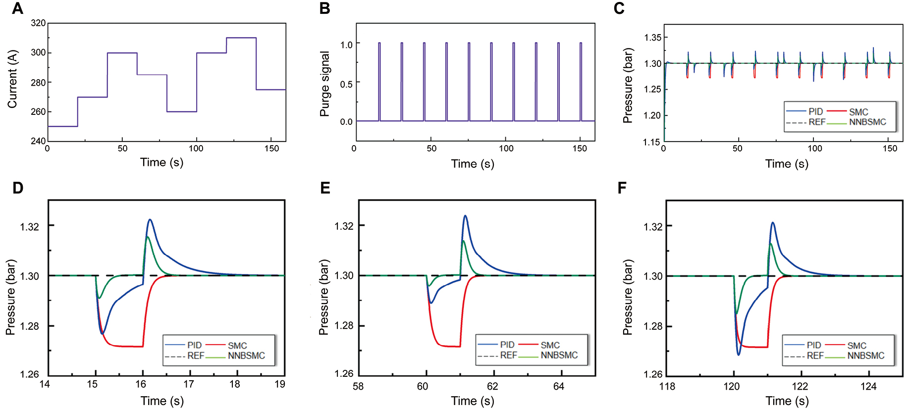
Figure 8C shows the control effect of PID/BSMC/NNBSMC controllers on the pressure of the hydrogen supply system of the fuel cell anode under load current fluctuation and periodic purge interference. In Figure 8D, it is evident that the NNBSMC controller is able to effectively compensate for the pressure fluctuations arising in the course of the purging procedure, while the BSMC controller, lacking compensatory measures, gives rise to a substantial pressure differential when the purging valve is in operation, a condition that impairs the stable operation of the fuel cell system. Figure 8E, F shows the control effect of the three controllers on the anode pressure when purging with an upward step current and purging with a downward step current, that is, when two external disturbances are present simultaneously. Due to the coupling relationship between the load current and the hydrogen flow rate, it is found that the step of the load current will have a certain compensation or amplification effect on the fluctuation of anode pressure during the purge process, but overall, the control performance exhibited by the NNBSMC controller is evidently superior to the other two types of controllers.
In an attempt to more authentically reflect the output performance characteristics of the fuel cell system during the actual driving process of a fuel cell vehicle, the present section employs the load current operating condition dataset gathered during the actual operational process from fuel cell hybrid electric vehicles reported in relevant reference documents for the purpose of validating the control performance of the proposed controller. This condition is the total current of the fuel cell and the power battery, and the actual current change rate of the vehicle fuel cell system will be much lower than the direct current (DC) bus current. The current in this working condition is scaled and limited to more than 120 A, so that the current is within the normal operating range of the fuel cell system model established in this paper, and at the same time, the ejector runs in reflux mode, resulting in insufficient hydrogen supply to the reactor and limited output performance.
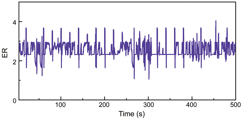
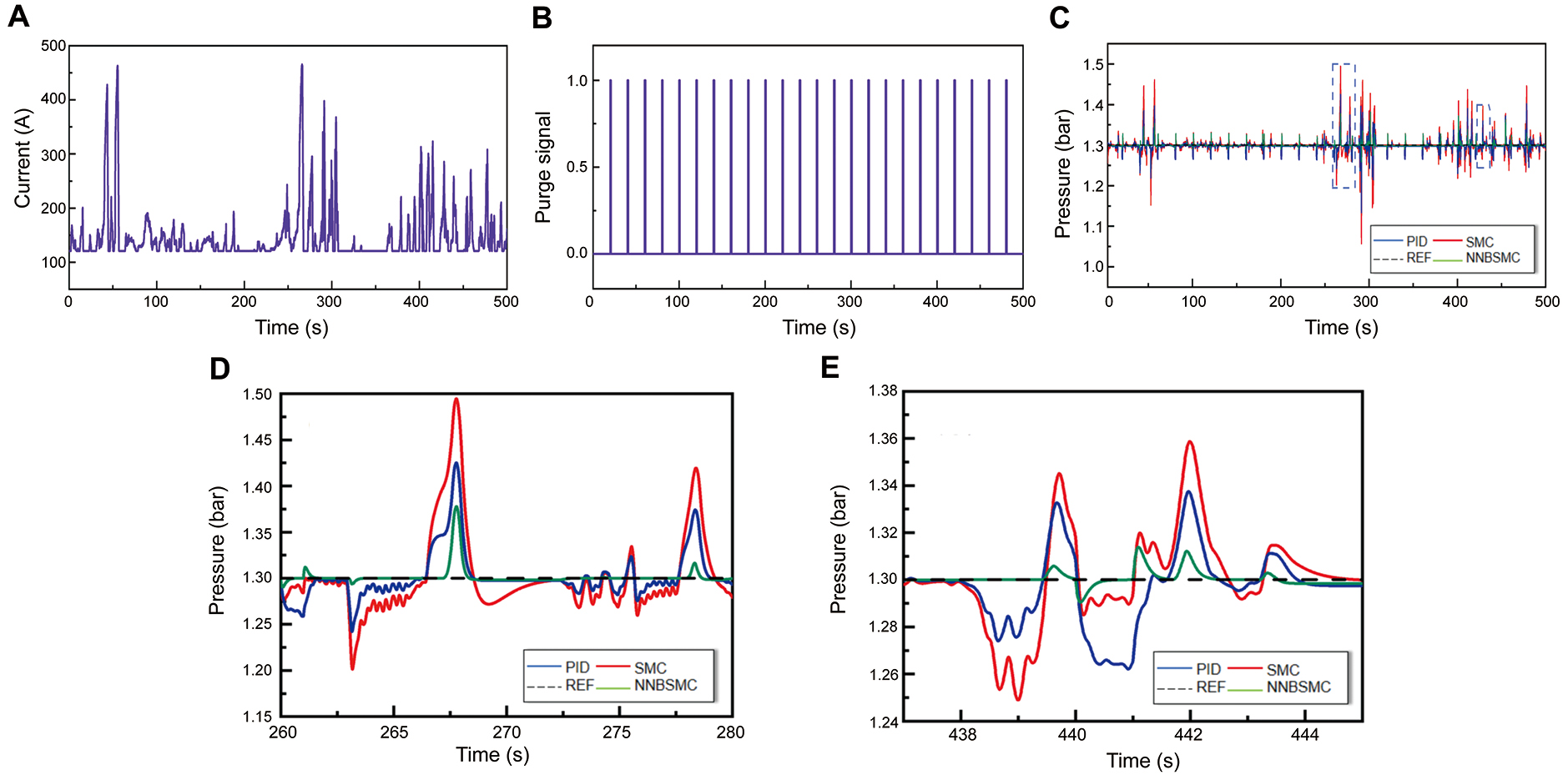
Figure 9A shows the current condition of the real car DC bus. The purge signal is shown in Figure 9B. Under this working condition, the control results of PID, SMC, and NNBSMC controllers for the system anode pressure are shown in Figure 9C. As can be seen from the overall trend in the figure, the PID controller has not achieved good results in controlling the anode hydrogen pressure under the condition of large current fluctuation and purge disturbance in real vehicle conditions, and frequent pressure fluctuation is not conducive to the stability of the output performance of the fuel cell stack. At the same time, the excessive pressure difference between the two poles will cause irreversible damage to the proton exchange membrane and the reactor. Figure 9D, E is a partial enlarged drawing of Figure 9C, from which it can be seen more clearly that the control effect of SMC and NNBSMC controllers is obviously better than that of PID controllers. In addition, in the case of external disturbances, the NNBSMC controller shows better performance and can effectively maintain the hydrogen pressure stability of the fuel cell, with the best robustness. Although the proposed controller achieves smoother pressure regulation compared with conventional sliding mode control, slight fluctuations remain because the switching mechanism is maintained to ensure robustness. The hydrogen stoichiometric ratio in the anode system under the NNBSMC controller is shown in Figure 10. It can be seen that in the entire operation process, the hydrogen stoichiometric ratio is basically maintained between 2 and 4, which can fully ensure the adequate hydrogen flow supply of the anode system to meet the normal operation needs of the fuel cell.
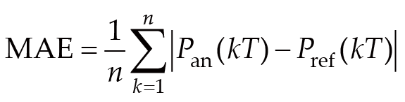
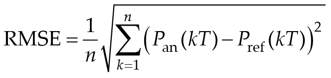
Comprehensively evaluate the control effects of the three controllers under real vehicle conditions. The dynamic performance indicators of the fuel cell anode hydrogen supply system are shown in Figure 11, which mainly include maximum tracking error (MAX_ERROR), mean absolute error (MAE), and root mean square error (RMSE). These indicators are defined as follows:(42)(43)(44)
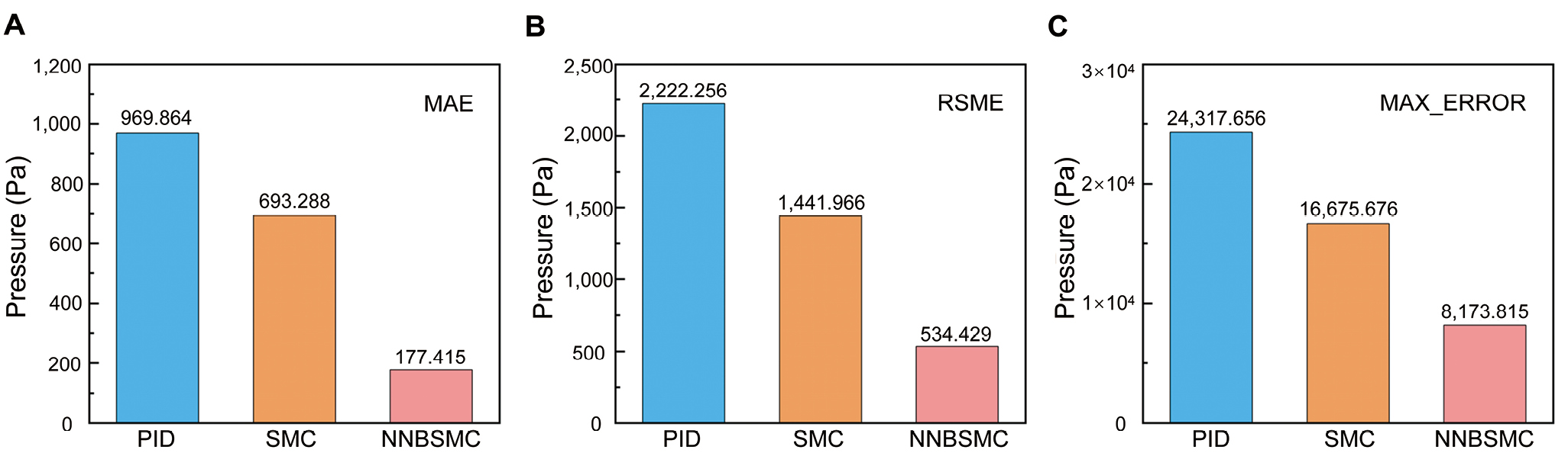
As illustrated in Figure 11, the three performance indicators of the NNBSMC controller are significantly better than the other two controllers, showing excellent control performance and robustness, which is of great significance for the gas pressure regulation of full-power fuel cell vehicles applied in real scenarios.
In this study, a dynamic model of a fuel cell anode based on a single injector that can be used in the hydrogen supply cycle is developed. Based on the actual bench data, the flow and pressure characteristics of the ejector model are verified. Then, a backstepping sliding mode controller is proposed to stabilize the anode pressure of the fuel cell. Considering that the necessary purge-induced gas flow disturbance during the working of the stack will have a significant impact on the dynamic characteristics of the anode pressure, the RBF neural network is further used to fit the compensation, and the control effect is verified under the current step condition and the real vehicle load condition combined with the backstepping sliding mode controller originally designed.
The simulation results show that: (1) in the scenario without purging operation, the BSMC scheme could show a better control effect than the PID controller and sliding mode controller commonly used in industry, and has better performance and robustness; (2) after adding periodic purging action, the NNBSMC controller can accurately compensate for the pressure fluctuations generated by the purging process, while the BSMC controller without compensation will cause the stack anode to produce a large pressure difference when the purging valve is purging, which is not conducive to the stable operation of the fuel cell; (3) under real vehicle load conditions, the BSMC controller incorporating an RBF neural network has better stability and target tracking performance than the traditional PID controller. The maximum tracking error is 8.173 kPa, the average error is 0.17 kPa, and the root-mean-square error is 0.53 kPa. These results confirm that the proposed control strategy is effective for managing hydrogen gas pressure dynamics in ejector-based anode recirculation systems, offering a practical solution for improving the stability and robustness of fuel cell systems under realistic driving conditions. Future research will focus on experimental validation of the proposed controller and further investigation of advanced adaptive control methods to improve practical applicability.
Caizhi Zhang: Investigation; conceptualization; data curation; writing – original draft. Yuanjie Gao: Investigation; formal analysis; visualization; validation. Yuan Feng: Methodology; software; investigation; writing – review & editing. Changhong Du: Resources; investigation; data curation. Tao Zeng: Validation; formal analysis; writing – review & editing. Junyu Yang: Investigation; data curation; visualization. Yuansong Li: Writing – review & editing; visualization; methodology. Dávid Kis: Formal analysis; software; validation; writing – review & editing. Quan Liao: Conceptualization; supervision; funding acquisition; project administration; writing – review & editing.
This work was partially supported by the Chengdu government, which focuses on the research of key technologies for high-capacity and intelligent efficient hydrogen refueling stations (Grant No. 2023-YF11-00039-HZ), Hangzhou Qianjiang Distinguished Experts (Caizhi Zhang), the central university funding (Grant No. 2024CDJZCQ-003), the State Key Laboratory of Mechanical Transmission in Chongqing University (Grant No. SKLMT-ZZKT-2022R02), the Automobile Collaboration Center Unveiling Project (Grant No. 2022CDJDX-004), and the Fundamental Research Funds for the Central Universities (Grant No. 2025CDJZKZCQ-16).
The data that support the findings of this study are available from the corresponding author upon reasonable request.
Y. D. Wang, Q. Meyer, K. Tang, et al., "Large-Scale Physically Accurate Modelling of Real Proton Exchange Membrane Fuel Cell with Deep Learning," Nature Communications 14 (2023): 745, https://doi.org/10.1038/s41467-023-35973-8.
J. Xu, C. Zhang, R. Fan, et al., "Modelling and Control of Vehicle Integrated Thermal Management System of PEM Fuel Cell Vehicle," Energy 199 (2020): 117495, https://doi.org/10.1016/j.energy.2020.117495.
L. Cai, C. Liang, C. Zhang, et al., "Design and Investigation of Novel Gradient Flow Fields for Proton Exchange Membrane Fuel Cell," International Journal of Heat and Mass Transfer 224 (2024): 125310, https://doi.org/10.1016/j.ijheatmasstransfer.2024.125310.
M. X. Li, Y. F. Bai, C. Z. Zhang, et al., "Review on the Research of Hydrogen Storage System Fast Refueling in Fuel Cell Vehicle," International Journal of Hydrogen Energy 44, no. 21 (2019): 10677–10693, https://doi.org/10.1016/j.ijhydene.2019.02.208.
D. Manzo, R. Thai, H. T. Le, and G. K. Venayagamoorthy, "Fuel Cell Technology Review: Types, Economy, Applications, and Vehicle-to-grid Scheme," Sustainable Energy Technologies and Assessments 75 (2025): 104229, https://doi.org/10.1016/j.seta.2025.104229.
Q. Su, J. Zhou, F. Yi, et al., "An Intelligent Control Method for PEMFC Air Supply Subsystem to Optimize Dynamic Response Performance," Fuel 361 (2024): 130697, https://doi.org/10.1016/j.fuel.2023.130697.
C. Jia, J. Zhou, H. He, et al., "A Novel Energy Management Strategy for Hybrid Electric Bus with Fuel Cell Health and Battery Thermal-and Health-constrained Awareness," Energy 271 (2023): 127105, https://doi.org/10.1016/j.energy.2023.127105.
D. Hu, Y. Wang, J. Li, J. Wang, and Q. Yang, "Energy Saving Control of Waste Heat Utilization Subsystem for Fuel Cell Vehicle," IEEE Transactions on Transportation Electrification 10, no. 2 (2023): 3192–3205, https://doi.org/10.1109/TTE.2023.3304844.
H. T. Zhao, M. Q. Yuan, Y. H. Peng, et al., "An Integrated Approach to Analyzing Matrix-crack-induced Stiffness Degradation and Medium Leakage in Linerless Composite Vessels," Composites Part A: Applied Science and Manufacturing 185 (2024): 108364, https://doi.org/10.1016/j.compositesa.2024.108364.
A. Priyam, "Hydrogen as an Alternative Fuel for Internal Combustion Engines: A Review," Sustainable Energy Technologies and Assessments 82 (2025): 104551, https://doi.org/10.1016/j.seta.2025.104551.
Z. Yang, Q. Du, Z. Jia, et al., "A Comprehensive Proton Exchange Membrane Fuel Cell System Model Integrating Various Auxiliary Subsystems," Applied energy 256 (2019): 113959, https://doi.org/10.1016/j.apenergy.2019.113959.
B. Wang, H. Deng, and K. Jiao, "Purge Strategy Optimization of Proton Exchange Membrane Fuel Cell with Anode Recirculation," Applied energy 225 (2018): 1–13, https://doi.org/10.1016/j.apenergy.2018.04.058.
Y. Song, L. Wang, L. Jia, and X. Wang, "Optimization and Performance Investigation of Confocal Twin-nozzle Ejector for PEMFC Hydrogen Supply and Recirculation System Under Actual Variable Operating Conditions," International Journal of Hydrogen Energy 50, Part B (2024): 1450–1464, https://doi.org/10.1016/j.ijhydene.2023.07.201.
X. Liang, H. Kang, J. Shen, Z. Li, and R. Zeng, "Review and Analysis of Hydrogen Recirculation Devices for Compact Vehicular Proton Exchange Membrane Fuel Cells," Journal of Power Sources 555 (2023): 232308, https://doi.org/10.1016/j.jpowsour.2022.232308.
C. Z. Zhang, X. J. Cao, P. Bujlo, et al., "Review on the Safety Analysis and Protection Strategies of Fast Filling Hydrogen Storage System for Fuel Cell Vehicle Application," Journal of Energy Storage 45 (2022): 103451, https://doi.org/10.1016/j.est.2021.103451.
X. Meng, H. Ren, X. Yang, T. Tao, and Z. Shao, "Experimental Study of Key Operating Parameters Effects on the Characteristics of Proton Exchange Membrane Fuel Cell with Anode Recirculation," Energy Conversion and Management 256 (2022): 115394, https://doi.org/10.1016/j.enconman.2022.115394.
Y. Liu, Z. Tu, and S. H. Chan, "Water Management and Performance Enhancement in a Proton Exchange Membrane Fuel Cell System Using Optimized Gas Recirculation Devices," Energy 279 (2023): 128029, https://doi.org/10.1016/j.energy.2023.128029.
C. Zhang, Y. Zhang, M. Fan, Y. Zhang, and D. Hao, "Analysis of the Standard System of China For Hydrogen Energy and Fuel Cell Vehicle Related Fields," Energy Proceedings 19 (2021): 394, https://doi.org/10.46855/energy-proceedings-9231.
H. Qing, M. Jia, C. Zhang, et al., "Visualization Analysis of the Tendency of Key Technology in Fuel Cell System for Vehicle Application: A Review," CHAIN 2, no. 1 (2025): 15–42, https://doi.org/10.23919/CHAIN.2025.000002.
Z. Yu, Y. Tian, J. Liu, and L. Wang, "Research on PEMFC Gas Supply System: from Structural Improvement to Advanced Control Strategies," Fuel 405, Part D (2026): 136582, https://doi.org/10.1016/j.fuel.2025.136582.
J. Q. Zhang, Y. Yan, C. Zhang, et al., "Properties Improvement of Composite Layer of Cryo-compressed Hydrogen Storage Vessel by Polyethylene Glycol Modified Epoxy Resin," International Journal of Hydrogen Energy 48, no. 14 (2023): 5576–5594, https://doi.org/10.1016/j.ijhydene.2022.11.138.
X. Z. Yu, J. W. Fan, Y. H. Zhou, et al., "Experimental Investigation of the Effect of Hydrogen Recirculation on the Performance of a Proton Exchange Membrane Fuel Cell," International Journal of Hydrogen Energy 47, no. 2 (2022): 1183–1191, https://doi.org/10.1016/j.ijhydene.2021.10.063.
T. Zeng, C. Z. Zhang, A. J. Zhou, et al., "Enhancing Reactant Mass Transfer Inside Fuel Cells to Improve Dynamic Performance via Intelligent Hydrogen Pressure Control," Energy 230 (2021): 120620, https://doi.org/10.1016/j.energy.2021.120620.
B. Zhang, D. Hao, J. Chen, et al., "Modeling and Decentralized Predictive Control of Ejector Circulation-based PEM Fuel Cell Anode System for Vehicular Application," Automotive Innovation 5, no. 3 (2022):333–345, https://doi.org/10.1007/s42154-022-00190-4.
J. He, J. Ahn, and S. Y. Choe, "Analysis and Control of a Fuel Delivery System Considering a Two-phase Anode Model of the Polymer Electrolyte Membrane Fuel Cell Stack," Journal of Power Sources 196, no. 10 (2011): 4655–4670, https://doi.org/10.1016/j.jpowsour.2011.01.019.
Y. Wang, G. Wu, and Y. Wang, "Modeling and Control for PEMFC Hydrogen Management Subsystem Based on Neural Network Compensation and Prescribed Tracking Accuracy," Fuel 352 (2023): 129019, https://doi.org/10.1016/j.fuel.2023.129019.
F. Chen, Y. Pei, J. Jiao, X. Chi, and Z. Hou, "Energy Flow and Thermal Voltage Analysis of Water-cooled PEMFC Stack Under Normal Operating Conditions," Energy 275 (2023):127254, https://doi.org/10.1016/j.energy.2023.127254.
X. Ye, T. Zhang, H. Chen, J. Cao, and J. Chen, "Fuzzy Control of Hydrogen Pressure in Fuel Cell System," International Journal of Hydrogen Energy 44, no. 16 (2019): 8460–8466, https://doi.org/10.1016/j.ijhydene.2019.02.020.
H. Yuan, H. Dai, W. Wu, J. Xie, J. Shen, and X. Wei, "A Fuzzy Logic PI Control with Feedforward Compensation for Hydrogen Pressure in Vehicular Fuel Cell System," International Journal of Hydrogen Energy 46, no. 7 (2021): 5714–5728, https://doi.org/10.1016/j.ijhydene.2019.02.020.
H. Wei, C. Du, F. Ke, J. Zhao, J. Zhao, and X. Li, "Research on Air Supply Management for a 100-kW Vehicle Fuel Cell System with Fuzzy Self-adaptive Anti-disturbance Controller," Fuel 400 (2025): 135718, https://doi.org/10.1016/j.fuel.2025.135718.
L. Hong, J. Chen, Z. Liu, L. Huang, and Z. Wu, "A Nonlinear Control Strategy for Fuel Delivery in PEM Fuel Cells Considering Nitrogen Permeation," International Journal of Hydrogen Energy 42, no. 2 (2017): 1565–1576, https://doi.org/10.1016/j.ijhydene.2016.07.240.
S. Quan, Y. X. Wang, X. Xiao, H. He, and F. Sun, "Feedback Linearization-based MIMO Model Predictive Control with Defined Pseudo-reference for Hydrogen Regulation of Automotive Fuel Cells," Applied Energy 293 (2021): 116919, https://doi.org/10.1016/j.apenergy.2021.116919.
Z. M. Liu, G. F. Chang, H. Yuan, et al., "Optimal Control for Hydrogen Exhaust of Fuel Cell Systems Integrating Deep Reinforcement Learning With Risk Protection," IEEE Transactions on Transportation Electrification 12, no. 4 (2026): 5589–5601, https://doi.org/10.1109/TTE.2026.3665600.
X. C. Ge, W. Y. Li, J. Li, et al., "Exhaust Strategy Optimization of Hydrogen Supply System for Vehicle Proton-Exchange Membrane Fuel Cell," Journal of Energy Engineering 152, no. 2 (2026): 04025121, https://doi.org/10.1061/JLEED9.EYENG-6256.
Y. F. Bai, C. Z. Zhang, H. Duan, et al., "Modeling and Optimal Control of Fast Filling Process of Hydrogen to Fuel Cell Vehicle," Journal of Energy Storage 35 (2021): 102306, https://doi.org/10.1016/j.est.2021.102306.
H. He, S. Quan, and Y. X. Wang, "Hydrogen Circulation System Model Predictive Control for Polymer Electrolyte Membrane Fuel Cell-based Electric Vehicle Application," International Journal of Hydrogen Energy 45, no. 39 (2020): 20382–20390, https://doi.org/10.1016/j.ijhydene.2019.12.147.
Z. Du, Q. Liu, X. Wang, and L. Wang, "Performance Investigation on a Coaxial-nozzle Ejector for PEMFC Hydrogen Recirculation System," International Journal of Hydrogen Energy 46, no. 76 (2021): 38026–38039, https://doi.org/10.1016/j.ijhydene.2021.09.048.
L. Chen, K. Xu, Z. Yang, Z. Yan, C. Zhai, and Z. Dong, "Optimal Design of a Novel Nested-nozzle Ejector for PEMFC's Hydrogen Supply and Recirculation System," International Journal of Hydrogen Energy 48, no. 70 (2023): 27330–27343, https://doi.org/10.1016/j.ijhydene.2023.03.403.
C. Z. Zhang, L. Y. Chen, L. Lu, et al., "The Experiment and the Control of Hydrogen Circulation of Fuel Cell Based on of Fuel Ejector: A Review," International Journal of Hydrogen Energy 50 (2024): 1415–1431, https://doi.org/10.1016/j.ijhydene.2023.10.307.
J. He, S. Y. Choe, and C. O. Hong, "Analysis and Control of a Hybrid Fuel Delivery System for a Polymer Electrolyte Membrane Fuel Cell," Journal of Power Sources 185, no. 2 (2008): 973–984, https://doi.org/10.1016/j.jpowsour.2008.09.011.
Y. Zhu and Y. Li, "New Theoretical Model for Convergent Nozzle Ejector in the Proton Exchange Membrane Fuel Cell System," Journal of Power Sources 191, no. 2 (2009): 510–519, https://doi.org/10.1016/j.jpowsour.2009.02.014.
J. T. Pukrushpan, H. Peng, and A. G. Stefanopoulou, "Control-oriented Modeling and Analysis for Automotive Fuel Cell Systems," Journal of Dynamic Systems, Measurement, and Control 126, no. 1 (2004): 14–25, https://doi.org/10.1115/1.1648308.
B. Deng, W. Huang, and Q. Jian, "An Open-Cathode PEMFC Efficiency Optimization Strategy Based on Exergy Analysis and Data-driven Modeling," Energy 264 (2023): 126148, https://doi.org/10.1016/j.energy.2022.126148.
M. Yu, C. Wang, L. Wang, X. Wang, and D. Li, "Auxiliary-Ejector-Based Hydrogen Recirculation System to Broaden PEMFC Operating Range," International Journal of Hydrogen Energy 57 (2024): 515–529, https://doi.org/10.1016/j.ijhydene.2024.01.046.
P. Jithesh, A. Bansode, T. Sundararajan, and S. K. Das, "The Effect of Flow Distributors on the Liquid Water Distribution and Performance of a PEM Fuel Cell," International journal of hydrogen energy 37, no. 22 (2012): 17158–17171, https://doi.org/10.1016/j.ijhydene.2012.08.058.
H. Zhuang, Q. Sun, Z. Chen, and X. Zeng, "Robust Adaptive Sliding Mode Attitude Control for Aircraft Systems Based on Back-stepping Method," Aerospace Science and Technology 118 (2021): 107069, https://doi.org/10.1016/j.ast.2021.107069.
Y. Hu, C. Zhang, X. Gong, J. Gao, L. Zhang, and H. Chen, "Design of a Nonlinear Dynamic Output Feedback Controller Based on a Fixed-time RBF Disturbance Observer for a PEMFC Air Supply System," Measurement 211 (2023): 112683, https://doi.org/10.1016/j.measurement.2023.112683.
H. W. Li, B. S. Xu, C. H. Du, and Y. Yang, "Performance Prediction and Power Density Maximization of a Proton Exchange Membrane Fuel Cell Based on Deep Belief Network," Journal of Power Sources 461 (2020): 228154, https://doi.org/10.1016/j.jpowsour.2020.228154.
E. Dehdarinejad and M. Bayareh, "Performance Analysis of a Novel Cyclone Separator Using RBFNN and MOPSO Algorithms," Powder Technology 426 (2023): 118663, https://doi.org/10.1016/j.powtec.2023.118663.
 Top