ContentsFigures & Tables
With the expanding scope of autonomous missions in complex scenarios, such as post-disaster rescue and field reconnaissance, there is an urgent demand for transportation platforms that possess high efficiency and environmental adaptability. Traditional single-mode platforms exhibit significant limitations in complex geographical environments. For instance, unstructured environments severely restrict the mobility of ground vehicles, while confined terrains, such as canyons or narrow valleys, constrain the take-off capabilities and the efficiency of large aircraft [1, 2]. Capable of operating across both domains, aerial-ground amphibious platforms have emerged as a promising solution and are regarded as the ultimate goal of the development [3]. Hybrid locomotion can allow robots to tackle more complex tasks in complex environments while achieving greater performance, such as improved energy efficiency. The rapid development of these platforms has been driven by advancements in electric propulsion, lightweight materials, and autonomous navigation systems [4]. In particular, distributed electric propulsion (DEP) technology has become a core technical direction for aerial-ground amphibious platforms, which adopts miniaturized electrically driven propulsors to more flexibly exploit the advantages of aero-propulsion coupling. Compared with conventional configurations, such systems have been reported to significantly improve propulsive efficiency, energy utilization, and tackle more complex tasks in complicated environments [5–7]. Due to the mobility and versatility of such aerial–ground amphibious platforms, they are particularly valuable in time-critical scenarios, such as medical delivery, material resupply, emergency rescue, and recovery after natural disasters [8, 9]. Therefore, the use of aerial-ground amphibious platforms is receiving increasing attention, leading to a surge in related innovative designs and technical solutions [10].
Currently, electric vertical take-off and landings (eVTOLs) can be broadly classified into two distinct categories: "ground-dominant" flying cars, which integrate road travel with flight capabilities, and "air-dominant" eVTOLs, which prioritize aerial mobility with minimal or no ground operation [11]. Regardless of their specific category, most aerial-ground amphibious platforms generally adopt a modular decoupled configuration. This approach essentially combines separate, single-function propulsion modules for driving and flying to achieve dual-domain capability. Consequently, it inevitably leads to duplicated actuators and redundant power-transmission paths between the two mobility modes. Examples include the Joby S4 [12], which uses wheels and six tilt-rotors to achieve land taxiing and air flight respectively; the Transition, which employs wheels and foldable wings powered by a hybrid combustion engine; Tsinghua University's "Mengshi" Flying Car [13], featuring a distributed six-rotor system coupled with an Ackermann steering chassis; Lilium Jet, which provides high redundancy with 36 ducted fans attached to its fixed wings [14]; Cobots, which can roll on the surface, fly in a flight array formation, and swim on or under liquid [15]; Skywalker, based on an off-the-shelf omnidirectional wheel, which proposes a unified controller qualified for high-speed air-ground hybrid trajectory tracking and smooth mode switching [16]; DoubleBee, consisting of two propellers mounted on tilting servo motors and two motor-driven wheels, which can traverse unstructured environments, fly over barriers, and climb steep or rough terrains [17]; and FSTAR, which is designed for climbing over slopes and is fitted with a sprawling mechanism and propellers that allow it to both run and fly using the same motors [18]. There are also other studies that adopt the leg-propeller or the leg-wing design, which effectively reduces structural weight [19–23]. Notably, most of these mainstream schemes adopt DEP architecture, but they split the DEP system into two completely independent sets for ground-wheeled drive and aerial flight, respectively. This decoupled application of DEP completely deviates from the original design intention of lightweight and high integration of DEP technology, and further aggravates the inherent defects of low integration, structural redundancy, and excessive mass. Such configurations often encounter suboptimal locomotion efficiency during ground operation due to increased mechanical complexity and energy dissipation. Furthermore, these decoupled wheel-propeller configurations are characterized by low integration and structural redundancy. The resulting weight penalty severely constrains the platform's maneuverability and payload capacity, especially in challenging environments such as narrow passages, muddy flats, and ravines.
To alleviate the structural redundancy and low integration inherent in modular designs, some recent studies have explored integrated wheel-propeller structures, focusing on the unified design of actuators for both driving and flying functions. Notable examples include the HyTAQ platform [24], which uses a cylindrical cage as the ground actuator for rolling and a quadrotor as the aerial actuator for flying; the Cyclorotor of Russian [25], achieving the integrated application of cylindrical wheels and multiple blades; the MTABot, which uses deformable wheels and propellers to achieve three modalities: rolling, climbing, and flying [26]; SytaB, which uses two propellers covered by cages, and these cages are used as part of the wheels [27]; Drivocopter, which also consists of four independently actuated spherical wheels to protect the propeller in collision [28]; and the M4 Robot [29], employing a ducted propeller as the integrated actuator, achieving mode switching through coordinated motor and servo control. These designs demonstrate that sharing mechanical structures between ground and aerial functions can significantly improve hardware integration. These studies suggest that platforms based on shared wheel–propeller structures can compress the power-transmission chain, reduce the number of dedicated actuators, and thus achieve higher structural integration and potentially lower system mass. Despite these advancements, a critical limitation persists: current integrated configurations require vertical take-off and landing (VTOL) for mode transition. They are unable to accomplish a seamless transition between sustained ground locomotion and aerial flight during motion. For post-disaster emergency rescue missions, the mandatory stop for mode switching not only wastes the critical golden rescue window for trapped personnel, but also exposes the platform to high risks of secondary disasters such as aftershocks and falling debris during the parking process; for narrow canyon reconnaissance and border patrol missions, most working areas have extremely limited space with no effective room for parking and static mode switching, hindering their effectiveness in meeting the demands of diverse and specialized tasks in complex operational environments. Furthermore, the adopted DEP still employs two independent power sources to drive two respective sets of matched actuators, while the inherent dead weight of the electric motors remains an unresolved issue.
To overcome the abovementioned technical bottleneck of DEP application in amphibious platforms, this study proposes a novel integrated wheel-propeller structure driven by a single, highly integrated power-transmission and drive system. By controlling the engagement and disengagement of electromagnetic clutches, the platform can switch seamlessly between ground-driving and aerial-flight modes. Furthermore, based on this integrated wheel-propeller structure, a configuration of an aerial-ground amphibious platform is designed, capable of performing VTOL, executing dynamic take-off and landing motion. The main contributions of this work are summarized as follows:
(1) A novel integrated wheel-propeller structure enabling power mode switching through the control of the electromagnetic clutch is designed.
(2) An aerial-ground amphibious platform based on eight integrated wheel-propeller structures is proposed, capable of performing both VTOL and dynamic take-off and landing motion.
(3) A dynamic model for the platform with feasibility validation conducted through simulation is established.
This study adopts the concept of distributed drive. First, the design of an integrated wheel-propeller structure is carried out, as illustrated in Figure 1A, B. Compared with conventional open propellers, ducted propellers achieve higher aerodynamic efficiency and lower noise levels at the same geometric size [30]. Furthermore, propellers without the protective cover are difficult to integrate with the wheels. Consequently, to minimize size and mass while maximizing structural simplicity, the wheel assembly was chosen for integrated design with a 120 mm compact ducted propeller.
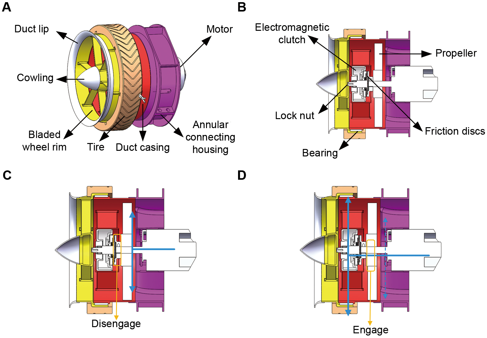
The integrated wheel-propeller structure comprises three primary assemblies: an electromagnetic clutch assembly, a ducted propeller and a motor assembly, and a wheel assembly. The bladed wheel rim and tire serve as the ground propulsion unit, generating driving force during locomotion. The ducted propeller serves as the aerial propulsion unit, providing tractive force during terrestrial locomotion. The electromagnetic clutch acts as the switching mechanism, directing the power source output to either the wheel assembly or the propeller assembly. By controlling the engagement status of the electromagnetic clutch, the operating state is switched between driving and flying modes, thereby achieving dual-domain (aerial and ground) mobility utilizing only a single power-transmission system. Additionally, an annular connecting housing featuring lug structures is integrated into the duct outer casing, facilitating the attachment of the integrated wheel-propeller structure to the platform frame. The operational principle of the integrated wheel-propeller structure is as follows:
Clutch-engaged state: upon engagement of the electromagnetic clutch, electromagnetic force causes the two toothed friction discs within the clutch to mesh, as illustrated in Figure 1C. The power generated by the motor drives the rotation of the ducted propeller. Simultaneously, through the meshed friction discs, power is transmitted to the wheel assembly, driving the rotation of the bladed wheel. A bearing positioned between the wheel and the duct's outer casing provides structural support and reduces rotational friction.
Clutch-disengaged state: when the electromagnetic clutch is disengaged, the two toothed friction discs separate, as illustrated in Figure 1D, interrupting the power flow to the wheel assembly. The motor's full output is dedicated to the ducted propeller. To optimize aerial performance, the duct inlet lip enhances intake efficiency, while the cowling is designed to minimize aerodynamic drag during high-speed rotation.
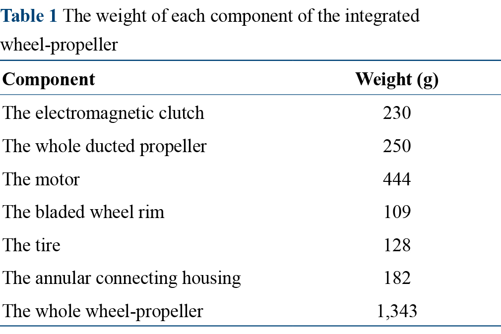
The weight of each component of this wheel-propeller is shown in Table 1. The traditional dual-motor system (444 × 2 = 888 g) has a higher total weight than the single-motor configuration with a clutch (444 + 230 = 674 g), while the single-motor integrated solution achieves a higher level of system integration. Moreover, due to the integrated design of the wheel-propeller structure, the weight of the platform can be reduced further.
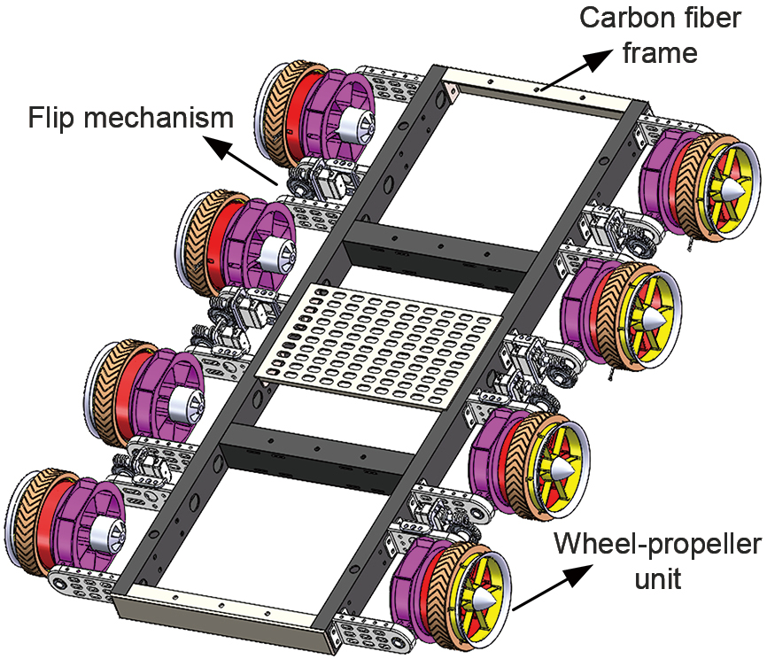
Based on the integrated wheel-propeller structure, we propose an aerial-ground amphibious platform with an eight-wheel-propeller unit configuration. Its primary components include wheel-propeller units, flip mechanisms, and a carbon fiber frame. Each wheel-propeller unit is connected to the carbon fiber airframe via a flip mechanism, as shown in Figure 2. To verify the non-collision performance of the wheel-propeller unit during the flipping mode-switching process, a systematic spatial interference check is detailed in the Supporting Information.
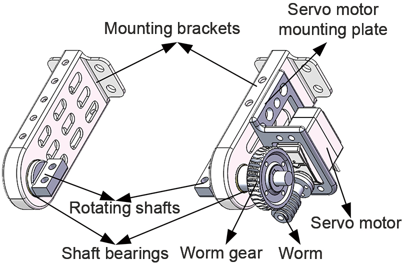
The flip mechanism comprises left and right mounting brackets for the wheel-propeller unit, rotating shafts, shaft bearings, and on one side a worm gear, worm, servo motor mounting plate, and servo motor, detailed in Figure 3. The mounting brackets are rigidly fixed to the main airframe, providing structural support for the wheel-propeller unit. Each bracket features a front hole housing a self-lubricating bearing. The rotating shaft is installed within these bearings and rigidly connected to both sides of the annular connecting housing on the wheel-propeller unit. The worm gear, worm, and servo motor, assembled on one side of the mechanism, enable a directional change of the drive force. The adopted worm gear pair has a lead angle smaller than the equivalent friction angle, which realizes reverse self-locking. The power can only be transmitted from the worm to the worm gear, and reverse drive from the worm gear to the worm cannot be achieved. Actuating the servo motor transmits power sequentially through the worm, worm gear, rotating shaft, and finally to the wheel-propeller unit. By controlling the servo motor according to the required operational state, the wheel-propeller unit can be selectively oriented either perpendicular or parallel to the ground.
Since landing is the reverse process of take-off and they share the same principle, this study details the mode transition principle solely for the take-off scenario. The platform's take-off process (Figure 4) includes both vertical take-off and dynamic take-off modes. The difference lies in the distinct clutch disengagement times, as follows:
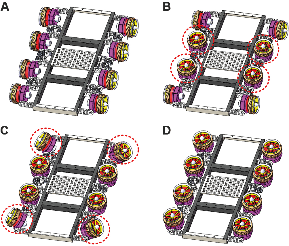
Vertical Take-off: (i) Ground driving state: the electromagnetic clutches are engaged, and all eight-wheel-propeller units are oriented perpendicular to the ground with their wheels in contact. Upon receiving the mode transition command, the platform stops its ground movement, interrupting all sustained ground locomotion. (ii) Wheel-propeller unit tilting state: the central four flip mechanisms actuate, reorienting four-wheel-propeller units parallel to the ground and generating lift. At the same time, the platform, like the wing-in-ground (WiG) vehicles, has a near-ground effect, providing additional lift [31]. The total lift enables the entire platform to take off. The other four wheel-propellers initially support the platform, and then they are later flipped over. Subsequently, all the electromagnetic clutches disengage, and the motors drive only the ducted propellers. (iii) Aerial hovering or flight state: the lift generated by all eight ducted propellers exceeds the platform's weight, enabling gradual ascent. By adjusting the rotational speed of all eight ducted propellers, the platform transitions into an aerial hovering or flight state as required.
Dynamic Take-off: (i) Ground driving state: the electromagnetic clutches are engaged, and all eight-wheel-propeller units are oriented perpendicular to the ground with their wheels in contact. The platform maintains continuous forward ground driving throughout the entire mode transition process, with no interruption to sustained ground locomotion. (ii) Central four-wheel-propeller unit tilting state: upon receiving the mode transition command, the flip mechanisms for the four central wheel-propeller units actuate, reorienting them parallel to the ground. The electromagnetic clutches of these four central units then disengage, and their motors drive only the ducted propellers. The four corner wheel-propeller units remain in the ground driving state to sustain continuous forward propulsion of the platform without stopping. (iii) Pre-take-off state: the rotational speed of the central ducted propellers is increased until the generated lift exceeds the platform's weight, initiating gradual ascent. During this gradual ascent, the flip mechanisms for the four corner units actuate, reorienting them parallel to the ground. Simultaneously, the ducted propellers on the corner units are activated to provide thrust. (iv) Aerial hovering or flight state: by adjusting the rotational speed of all eight ducted propellers, the platform completes the seamless non-stop drive-to-fly transition and transitions into an aerial hovering or flight state as required.
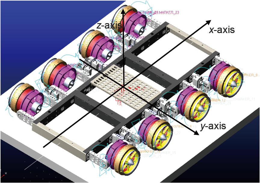
A dynamic simulation model of the complete aerial-ground amphibious platform was developed in automatic dynamic analysis of mechanical systems (ADAMS). The simulation analysis focused on the dynamic take-off process. Three types of kinematic joints were defined in the model:
(i) Revolute joints at the central axis of each ducted propeller (serving as the rotation axis for the propeller);
(ii) Revolute joints at the rotation axis of each flip mechanism;
(iii) Fixed joints connecting the platform to the ground reference, as shown in Figure 5.
To ensure high-fidelity reproduction of relative motions and force interactions between components, appropriate drive functions were applied according to the prescribed dynamic take-off sequence with global gravity and wheel–ground contact forces integrated into the simulation.
During the initial simulation phase, all eight-wheel-propeller units are oriented perpendicular to the ground. Under the action of the driving function, the units propel the entire platform forward. At the pre-defined drive-to-fly transition point of the fifth second, the flip drive function is activated for the four central wheel-propeller units. Within this transition interval, the flip angle of these four central units gradually increases until they reach a 90° reorientation, parallel to the ground. Concurrently, their functional role transitions from providing support and propulsion during ground locomotion to functioning as structures housing ducted propeller systems that generate lift during flight. This process enables the entire platform to achieve a gradual and stable transition from the ground driving process to the aerial flight process.
Simulation results illustrate the platform's displacement and velocity along the x-axis, as illustrated in Figure 6A (driving direction). The platform traveled from 57 to 3,043 mm within 3 s, reaching a velocity of approximately 1,048 mm s−1, which aligns with the preset wheel rotational speed of 800 (°) s−1.
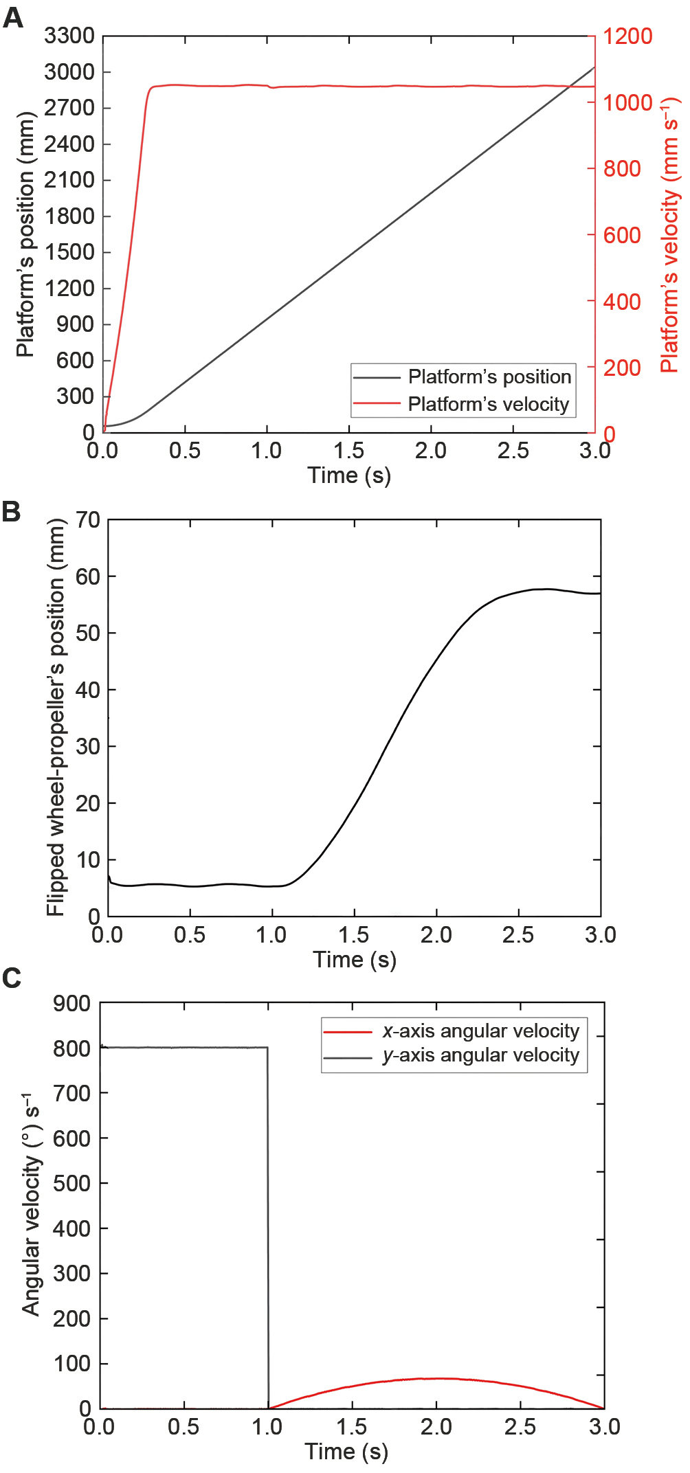
Furthermore, analysis was conducted on one of the four central wheel-propeller units, resulting in the curve of its z-axis position (vertical direction) versus time, as illustrated in Figure 6B, and the curves of its angular velocity about the x-axis and y-axis versus time, as illustrated in Figure 6C. During the 0–1 s interval, the z-axis position remained constant, and its y-axis angular velocity was maintained at 800 (°) s−1. In the 1–3 s interval, the z-axis position initially increased to 58 mm before gradually decreasing to 57 mm. Simultaneously, its angular velocity about the x-axis increased from 0 (°) s−1, reached a peak of 68 (°) s−1 at 2 s, and subsequently decreased back to 0 (°) s−1 by the end of this interval. Finally, at the 3 s, its angular velocities about both the x-axis and the y-axis remained at 0 (°) s−1.
The simulation results validate the underlying working principle of the platform's transition from the ground driving state to the aerial flight state, demonstrating its capability to smoothly and successfully execute the dynamic take-off process.
To address the critical challenge of low integration, structural redundancy, and excessive weight inherent in conventional decoupled designs for aerial-ground amphibious platforms, this paper proposes a novel integrated architecture. The core innovation presented is the design of a shared wheel-propeller integrated structure, which utilizes a single, highly integrated powertrain, and achieves reliable mode switching via a precisely controlled electromagnetic clutch. Based on this structure, an eight-wheel-propeller platform configuration is proposed, capable of both VTOL and dynamic rolling take-off and landing maneuvers. The established dynamic model and corresponding simulation results confirm the feasibility, stability, and effectiveness of the proposed integrated architecture and mode transition strategy. This research provides a viable and significant technical pathway for developing next-generation lightweight, highly integrated aerial-ground amphibious platforms, and has important engineering application value for advancing the practical application of such transformative transportation equipment.
Peng Dong: Writing-original draft; resources; methodology; funding acquisition. Wantong Zhao: Writing-original draft; formal analysis; data curation; software. He Zou: Investigation; formal analysis; data curation. Rongze Yi: Investigation; software; project administration; validation. Cunhao Zhang: Investigation; methodology; formal analysis. Haiying Lin: Funding acquisition; conceptualization. Huijun Yue: Investigation; formal analysis. Junbin Lai: Writing-review & editing; project administration; methodology; validation; supervision.
This work was supported by the National Key Laboratory of Multi-Perch Vehicle Propulsion Systems (Grant No. 2024-CXPT-GF-JJ-091-02-01).
The data that support the findings of this study are available from the corresponding author upon reasonable request.
Additional supporting information can be found online in the Supporting Information section.
A. Fabris, S. Kirchgeorg, and S. Mintchev, "A Soft Drone with Multi-modal Mobility for the Exploration of Confined Spaces," in Proceedings of the IEEE International Symposium on Safety, Security, and Rescue Robotics (SSRR), 48–54, IEEE, 2021, https://doi.org/10.1109/SSRR53300.2021.9597683.
L. Quan, L. Han, B. Zhou, S. Shen, and F. Gao, "Survey of UAV Motion Planning," IET Cyber-Systems and Robotics 2, no. 1 (2020): 14–21, https://doi.org/10.1049/iet-csr.2020.0004.
K. Rajashekara, Q. Wang, and K. Matsuse, "Flying Cars: Challenges and Propulsion Strategies," IEEE Electrification Magazine 4, no. 1 (2016): 46–57, https://doi.org/10.1109/MELE.2015.2509901.
N. P. Hariram, A. Megalingam, and K. Sudhakar, "Flying Cars and Hyperloops: A Glimpse into the Future Sustainable Vehicles," Sustainable Energy Technologies and Assessments 75 (2025): 104196, https://doi.org/10.1016/j.seta.2025.104196.
A. Kasliwal, N. J. Furbush, J. H. Gawron, et al., "Role of Flying Cars in Sustainable Mobility," Nature Communications 10 (2019): 1555, https://doi.org/10.1038/s41467-019-09426-0.
A. T. Wick, J. R. Hooker, and C. H. Zeune, "Integrated Aerodynamic Benefits of Distributed Propulsion," paper presented at the 53rd AIAA Aerospace Sciences Meeting, Kissimmee, USA, January 5–9, 2015, https://doi.org/10.2514/6.2015-1500.
H. J. Terry Suh, X. Xiong, A. Singletary, A. D. Ames, and J. W. Burdick, "Energy-Efficient Motion Planning for Multi-Modal Hybrid Locomotion," in Proceedings of the 2020 IEEE/RSJ International Conference on Intelligent Robots and Systems (IROS), 7027–7033, IEEE, 2020, https://doi.org/10.1109/IROS45743.2020.9340761.
A. P. Cohen, S. A. Shaheen, and E. M. Farrar, "Urban Air Mobility: History, Ecosystem, Market Potential, and Challenges," IEEE Transactions on Intelligent Transportation Systems 22, no. 9 (2021): 6074–6087, https://doi.org/10.1109/TITS.2021.3082767.
H. Wei, B. Lou, Z. Zhang, B. Liang, F. Y. Wang, and C. Lv, "Autonomous Navigation for eVTOL: Review and Future Perspectives," IEEE Transactions on Intelligent Vehicles 9, no. 2 (2024): 4145–4171, https://doi.org/10.1109/TIV.2024.3352613.
G. Pan and M. S. Alouini, "Flying Car Transportation System: Advances, Techniques, and Challenges," IEEE Access 9 (2021): 24586–24603, https://doi.org/10.1109/ACCESS.2021.3056798.
N. Swaminathan, S. R. P. Reddy, K. RajaShekara, and K. S. Haran, "Flying Cars and eVTOLs–Technology Advancements, Powertrain Architectures, and Design," IEEE Transactions on Transportation Electrification 8, no. 4 (2022): 4105–4117, https://doi.org/10.1109/TTE.2022.3172960.
A. M. Stoll and J. Bevirt, "Development of eVTOL Aircraft for Urban Air Mobility at Joby Aviation," paper presented at the Vertical Flight Society 78th Annual Forum & Technology Display, Texas, USA, May 10–12, 2022, https://doi.org/10.4050/F-0078-2022-17528.
Q. Tan, X. Zhang, H. Liu, S. Jiao, M. Zhou, and J. Li, "Multimodal Dynamics Analysis and Control for Amphibious Fly-Drive Vehicle," IEEE/ASME Transactions on Mechatronics 26, no. 2 (2021): 621–632, https://doi.org/10.1109/TMECH.2021.3056095.
P. Marques, "Urban Air Mobility Aircraft -A fusion of Art and Technology," paper presented at the IEEE Aerospace Conference, Montana, USA, March 6–13, 2021.
A. Tagliabue, S. Schneider, M. Pavone, and A. Agha-mohammadi, "Shapeshifter: A Multi-Agent, Multi-Modal Robotic Platform for Exploration of Titan," in Proceedings of the IEEE Aerospace Conference, 1–13, IEEE, https://doi.org/10.1109/AERO47225.2020.9172739.
N. Pan, J. Jiang, R. Zhang, C. Xu, and F. Gao, "Skywalker: A Compact and Agile Air-Ground Omnidirectional Vehicle," IEEE Robotics and Automation Letters 8, no. 5 (2023): 2534–2541, https://doi.org/10.1109/LRA.2023.3256920.
M. Cao, X. Xu, S. Yuan, K. Cao, K. Liu, and L. Xie, "DoubleBee: A Hybrid Aerial-Ground Robot with Two Active Wheels," in Proceedings of the IEEE/RSJ International Conference on Intelligent Robots and Systems (IROSx), 6962–6969, IEEE, 2023, https://doi.org/10.1109/IROS55552.2023.10341984.
N. B. David, and D. Zarrouk, "Design and Analysis of FCSTAR, a Hybrid Flying and Climbing Sprawl Tuned Robot," IEEE Robotics and Automation Letters 6, no. 4 (2021): 6188–6195, https://doi.org/10.1109/LRA.2021.3077851.
A. Ramezani, P. Dangol, E. Sihite, A. Lessieur, and P. Kelly, "Generative Design of NU's Husky Carbon, A Morpho-Functional, Legged Robot," in Proceedings of the IEEE International Conference on Robotics and Automation (ICRA), 4040–4046, IEEE, 2021, https://doi.org/0.1109/ICRA48506.2021.9561196.
K. Peterson and R. S. Fearing, "Experimental Dynamics of Wing Assisted Running for a Bipedal Ornithopter," in Proceedings of the IEEE/RSJ International Conference on Intelligent Robots and Systems, 5080–5086, IEEE, 2011, https://doi.org/10.1109/IROS.2011.6095041.
K. Peterson, P. Birkmeyer, R. Dudley, and R.S. Fearing, "A Wing-Assisted Running Robot and Implications for Avian Flight Evolution," Bioinspiration & Biomimetics 6, no. 4 (2011): 046008, https://doi.org/10.1088/1748-3182/6/4/046008.
J. B. Richard, J. B. Frank, V. Ravi, G. I. Peter, and D. Q. Roger, "A Biologically Inspired Micro-Vehicle Capable of Aerial and Terrestrial Locomotion," Mechanism and Machine Theory 44, no. 3 (2009): 513–526, https://doi.org/10.1016/j.mechmachtheory.2008.08.008.
M. Zhao, T. Anzai, and T. Nishio, "Design, Modeling, and Control of a Quadruped Robot SPIDAR: Spherically Vectorable and Distributed Rotors Assisted Air-Ground Quadruped Robot," IEEE Robotics and Automation Letters 8, no. 7 (2023): 3923–3930, https://doi.org/10.1109/LRA.2023.3272285.
A. Kalantari and M. Spenko, "Modeling and Performance Assessment of the HyTAQ, a Hybrid Terrestrial/Aerial Quadrotor," IEEE Transactions on Robotics 30, no. 5 (2014): 1278–1285, https://doi.org/10.1109/TRO.2014.2337555.
Y. Zhang, Y. Qian, and W. Zhuge, "Unsettled Topics Concerning Flying Cars for Urban Air Mobility," SAE Research Report (2021): EPR2021011, https://doi.org/10.4271/EPR2021011.
K. Shi, Z. Jiang, L. Ma, L. Qi, and M. Jin, "MTABot: An Efficient Morphable Terrestrial-Aerial Robot with Two Transformable Wheels," IEEE Robotics and Automation Letters 9, no. 2 (2024): 1875–1882, https://doi.org/10.1109/LRA.2024.3349962.
J. Yang, Y. Zhu, L. Zhang, Y. Dong, and Y. Ding, "SytaB: A Class of Smooth-Transition Hybrid Terrestrial/Aerial Bicopters," IEEE Robotics and Automation Letters 7, no. 4 (2022): 9199–9206, https://doi.org/10.1109/LRA.2022.3190099.
A. Kalantari, T. Thomas, K. leon, et al., "Drivocopter: A Concept Hybrid Aerial/Ground Vehicle for Long-Endurance Mobility," IEEE Aerospace Conference, Montana, USA, March 1–10, 2020, https://doi.org/10.1109/AERO47225.2020.9172782.
E. Sihite, A. Kalantari, R. Nemovi, A. Ramezani, and M. Gharib, "Multi-Modal Mobility Morphobot (M4) with Appendage Repurposing for Locomotion Plasticity Enhancement," Nature communications 14, no. 1 (2023): 3323, https://doi.org/10.1038/s41467-023-39018-y.
A. T. Perry, P. J. Ansell, and M. F. Kerho, "Aero-Propulsive and Propulsor Cross-Coupling Effects on a Distributed Propulsion System," Journal of Aircraft 55, no. 6 (2018): 2179–2572, https://doi.org/10.2514/1.C034861.
N.V. Kornev and K. Matveev, "Complex Numerical Modeling of Dynamics and Crashes of Wing-in-Ground Vehicles," paper presented at the 41st Aerospace Sciences Meeting and Exhibit, Reno, USA, January 6–9, 2003, https://doi.org/10.2514/6.2003-600.
 Top
Top