ContentsFigures & Tables
Lithium-ion batteries (LIBs), owing to their lightweight design and high energy density, are widely used in various fields such as portable devices, wearable technologies, and electric vehicles (EVs) [1, 2]. EVs, in particular, also demand batteries with long cycle life, high safety, and a broad operating temperature range [3–5]. However, the use of volatile and flammable ester-based electrolyte solvents in LIBs introduces significant safety concerns, such as gas generation, electrolyte leakage, and even the risk of combustion or explosion [6]. Additionally, the relatively narrow electrochemical window of organic electrolytes, which are prone to oxidation and decomposition under high voltage, restricts the application of high-voltage cathode materials, hindering the potential improvement in energy density [7]. To overcome the challenges posed by liquid electrolytes (LEs) and break through the practical energy density barrier of 300 W·h·kg–1 [8], solid electrolytes (SEs) have gained increasing attention in recent years.
All-solid-state batteries (ASSBs) replace traditional organic liquid electrolytes with high-temperature-resistant, non-flammable SEs, significantly enhancing the battery's safety performance [9]. Additionally, because the solid electrolyte separates the anode and cathode, it prevents internal short circuits within the battery, eliminating the need for a separator [10]. As the thickness of the solid electrolyte membrane decreases, the energy density of ASSBs can be greatly improved. However, due to the absence of liquid components, poor solid-solid interface contact can lead to rapid capacity degradation during cycling. Laboratories often apply pressures exceeding hundreds of megapascals using specialized molds to ensure effective interface contact during cycling, improving the rate capability and cycle stability of ASSBs and delaying capacity fade [11]. These molded batteries are typically small in size, with electrodes often having diameters ranging from 10 to 20 mm. For lithium metal anodes, the electrode thickness usually exceeds 200 μm to provide sufficient lithium sources. However, the complex and bulky fixtures used significantly reduce the energy density of ASSBs, and such batteries are typically only used in laboratory environments for concept validation [12]. While these ASSBs can power miniature electronic devices, they are not suitable for large-scale practical applications [13]. To be applied in fields such as EVs, larger battery packaging formats are required.
In traditional LIBs, the mainstream battery shapes can be categorized into three types: cylindrical, prismatic, and pouch cells. Since ASSBs require high external stacking pressure, only pouch cells, which are wrapped in a flexible aluminum-plastic film, can meet this requirement. Considering the brittle nature of inorganic solid electrolytes and the characteristics of solid-solid interface contact [14], the stacking method is currently the only technology capable of assembling ASSBs, which also limits the use of the winding method commonly employed in cylindrical and prismatic cells [15]. For batteries larger than 1 A·h, pouch cells generally have a higher energy density compared to cylindrical and prismatic cells. This is primarily due to the lightweight aluminum-plastic film, which maximizes the specific energy density of the battery at the cell level [16]. To meet the demands of practical applications, pouch cells must also be designed to further enhance energy density. This includes reducing the proportion of inactive electrode materials, employing dual-sided coatings, increasing the loading amount, and ensuring that the thickness of the lithium metal anode is less than 40 μm [17]. The manufacturing of large-capacity pouch cells is challenging and requires higher standards of production equipment and environments. In practical use, issues such as the application of pressure, uneven distribution of electrode active materials, and current density may become dominant factors contributing to the failure of pouch cells, resulting in significantly worse cycle performance compared to molded cells [18]. Some researchers suggest that pouch cells are a reasonable manufacturing approach, while prismatic cells are a more suitable testing method. This can be achieved by immersing pouch cells, sealed with aluminum-plastic films, into prismatic casings filled with dielectric fluids such as deionized water, and ensuring that the prismatic casing can withstand 2–4 MPa of isostatic pressure during testing [19].
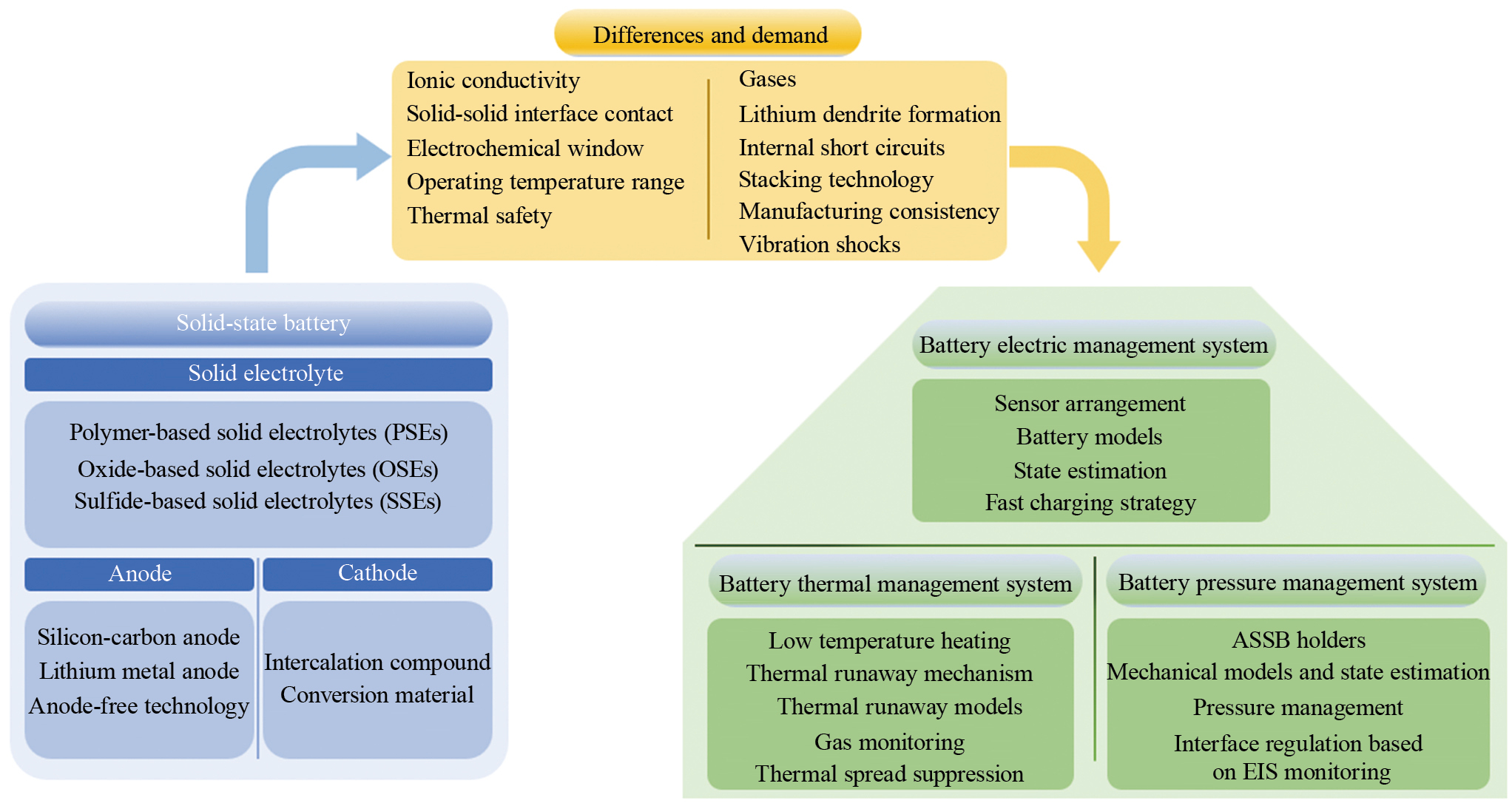
As shown in Fig. 1, in this review, we first introduce the background of battery technology development and the packaging formats of ASSBs. The second section discusses the advantages and disadvantages of polymer-based, oxide-based, and sulfide-based solid electrolytes, as well as advanced anode and cathode technologies suitable for high-specific-capacity ASSBs. It focuses on pouch-packaged ASSBs, highlighting the progress made in laboratory settings. The third section compares ASSBs with traditional LIBs, highlighting the differences and characteristics that present new demands and challenges for all-solid-state battery management system (ASSBMS). The fourth section constructs the ASSBMS from the perspectives of electrical, thermal, and pressure dimensions, focusing on the differences and improvements required compared to traditional battery management systems (BMS). Finally, the review summarizes the potential issues that may arise during the development of ASSBMS systems and outlines the future directions for their advancement.
PSEs are formed by the complexation of polymer matrixes with alkali metal salts, which are easy to prepare and offer high safety and good electrode compatibility. The excellent flexibility of PSEs allows pouch cells to continue functioning normally even after bending, which is not the case with inorganic solid electrolytes [20]. Moreover, the outstanding viscoelasticity of PSEs helps mitigate the separation between the electrode and electrolyte during battery cycling, which is beneficial for reducing charge transfer resistance and enhancing interface stability.
However, PSEs have extremely low ionic conductivity at room temperature. For instance, poly(ethylene oxide) (PEO)-based PSEs, due to their high crystallinity, have an ionic conductivity of only 10–6 to 10–7 S·cm–1 at 25 °C [21], which is much lower than that of LEs. As a result, batteries using PSEs often need to operate at temperatures between 60–80°C to ensure that the ionic conductivity reaches 10–4 S·cm–1. To enhance the ionic conductivity of PSEs, alternative polymer matrices, such as PVDF, which has a relatively high dielectric constant (ε=8.4), can be used to increase the solubility of alkali metal salts, allowing the ionic conductivity to reach 10–4 S·cm–1 even at room temperature [22]. Additionally, single-ion polymers, which fix anions to the polymer chain, can be employed to improve the lithium-ion transference number and conductivity [23].
In addition, PSEs have poor mechanical strength, which may affect the long-term stability and safety of the battery [24]. Their low elastic modulus fails to effectively suppress the formation of lithium dendrites, and their poor high-voltage stability limits compatibility with high-voltage cathode materials. To address these shortcomings, composite solid electrolytes (CSEs) containing inorganic solid electrolytes can be used to improve PSEs. By incorporating inorganic fillers into the polymer matrixes, CSEs can enhance ionic conductivity, mechanical strength, widen the electrochemical window, increase compatibility with cathode materials, and reduce interfacial resistance. The addition of inert fillers, such as SiO2, Al2O3, and TiO2, although not directly involved in Li⁺ transport, can reduce the crystallinity of the polymer, promote the dissociation of lithium salts, and improve the transference number of lithium ions. Active fillers, such as oxide or sulfide solid electrolyte particles, not only reduce the crystallinity of the polymer but also participate in the transport of lithium-ions [25].
Quasi-solid-state batteries are formed by adding 5 wt%–10 wt% LEs to ASSBs to enhance the wettability between the electrode and electrolyte interface. PSEs are currently the most commercially viable solid electrolytes [26], enabling the production of quasi-solid-state or all-solid-state batteries using existing lithium-ion battery manufacturing equipment. Designing and developing ASSBMS tailored to the characteristics of PSEs should be a key focus in the medium to short term. Lu et al. [27] developed a 2 A·h quasi-solid-state battery by injecting polyethylene glycol diacrylate (PEGDA) dissolved in LEs into a NCM811|Gr-Si pouch dry cell, and then in situ polymerization it at 60 °C using a thermal initiator (Fig. 2(a)). After 500 cycles at 0.5 C, the battery maintained 82.2% capacity, with a coulombic efficiency of up to 99.8% (Fig. 2(b)). The protective film formed at the electrode-electrolyte interface through in situ polymerization can suppress electrode damage caused by lithium insertion and extraction, facilitating the use of high-capacity anodes and cathodes and breaking through the upper limit of energy density in LIBs. Additionally, the strong interfacial adhesion between PSEs and the electrodes allows the assembled battery to operation without the need for additional high-pressure application.
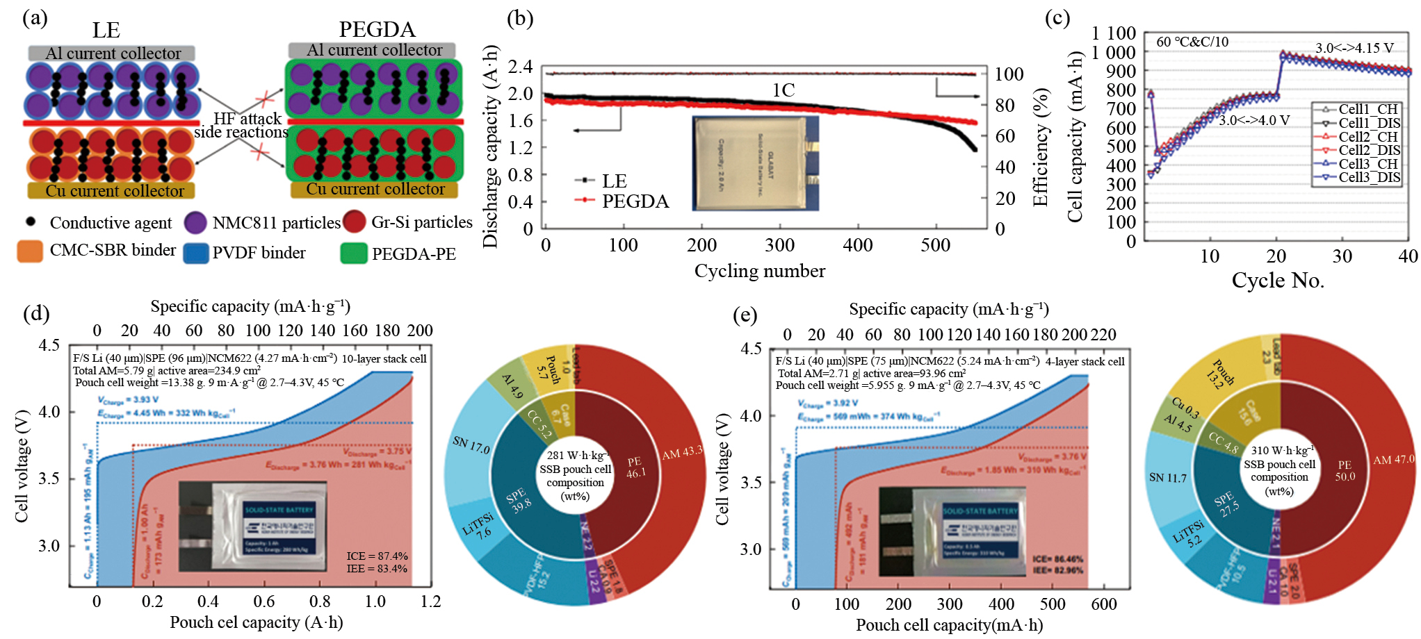
The in-situ polymerization strategy is simple, efficient, and suitable for mass production. It is fully compatible with traditional LIBs manufacturing processes, allowing the technology to be introduced into existing production lines without large-scale adjustments. This will significantly reduce the capital investment required for equipment modifications and save production costs [29]. However, this in-situ polymerization technology still utilizes ester-based liquid organic solvents, which do not entirely eliminate the safety concerns associated with them. Zhang et al. [28] used a PEO-LiTFSI polymer matrix doped with lithium-ion conductive glass-ceramics (LICGC) as CSEs to prepare three 1 A·h all-solid-state NMC622|LICGC@PEO-LiTFSI|MCMB pouch battery. In long-term cycling without added liquid electrolyte or external pressure, the battery exhibited a capacity loss of about 0.4% per cycle, with a coulombic efficiency of approximately 99.6% (Fig. 2(c)). However, due to the thick CSEs membrane (70 μm), higher interfacial resistance, and an electrode structure that still needs optimization, the energy density was only 70 W·h·kg–1, which is lower than that of liquid electrolyte-based lithium-ion batteries (~250 W·h·kg–1). To improve the energy density of ASSBs, Lee et al. [12] proposed design principles from the microelectrode to the macro cell level. They employed warm isostatic pressing (WIP) technology and a bipolar stacking structure to prepare 1 A·h and 0.5 A·h NCM622|PVDF-HFP-LiTFSI-SN|Li all-solid-state pouch batteries, achieving energy densities of 280 W·h·kg–1 and 310 W·h·kg–1 (Figs. 2(d) and (e)), respectively.
OSEs offer high mechanical strength, a wide electrochemical window, excellent thermal stability, and acceptable ionic conductivity. OSEs can be categorized into garnet-type Li7La3Zr2O12 (LLZO), NASICON-type Li1+xAlxTi2–x(PO4)3 (LATP) and Li1+xAlxGe2–x(PO4)3 (LAGP), as well as perovskite-type Li3xLa2/3–xTiO3(LLTO).
Garnet-type LLZO exhibits high ionic conductivity (10–3–10–4 S·cm–1) and excellent stability with lithium. However, its performance deteriorates significantly in humid environments, necessitating processing in dry, inert atmospheres, which hinders its scalability for practical mass production. NASICON-type LATP and LAGP possess a wide electrochemical window and good air stability, but LAGP can be reduced by lithium, leading to increased interfacial resistance and even internal short circuits [30]. Perovskite-type LLTO demonstrates excellent bulk ionic conductivity (~10–3 S·cm–1). However, grain boundary resistance limits its effective ionic conductivity to 10–5–10–6 S·cm–1. Additionally, LLTO has poor wettability with lithium metal, which can promote lithium dendrite growth during charge-discharge cycling, potentially causing internal short circuits. Furthermore, Ti⁴⁺ in LLTO is susceptible to reduction by commercial LFP cathodes, restricting its applicability [31].
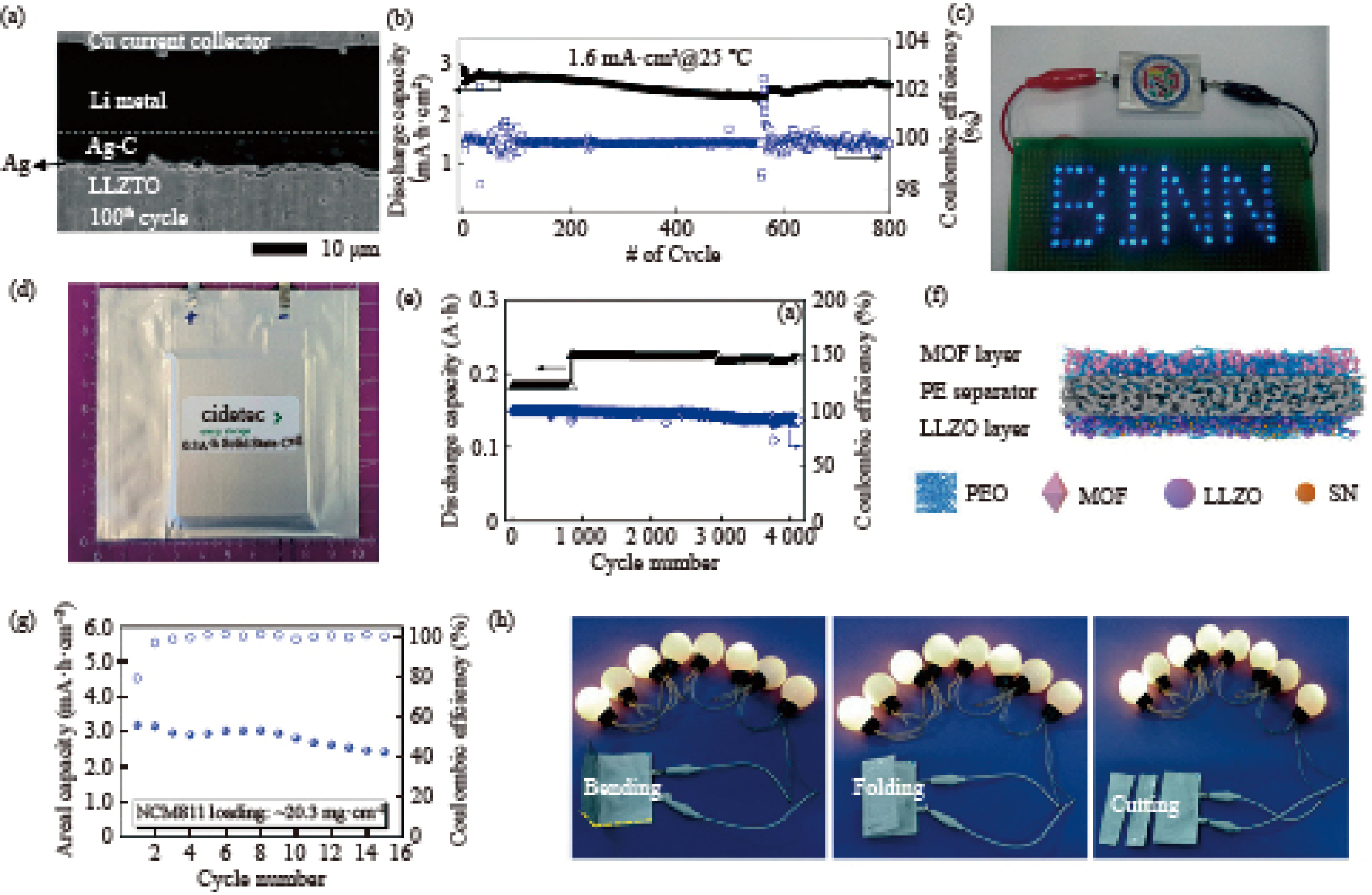
Although OSEs have a higher Young's modulus compared to PSEs, which are believed to suppress lithium dendrite growth. The grain boundaries in ceramic OSEs provide a path for dendrite growth, failing to effectively prevent it. This can lead to the fracture of OSEs and short-circuiting of the batteries. Kim et al. [32] reduced the contact resistance between the solid-solid interface by spraying a nanoscale-thickness silver layer on the surface of LLZTO and introducing a silver-carbon (Ag-C) composite intermediate layer between the electrolyte and the lithium-metal anode, which effectively regulated the stripping/plating behaviors of lithium and avoided direct contact between the lithium metal and the LLZTO, inhibiting the generation and penetration of lithium dendrites (Fig. 3(a)). Li|Ag-C/Ag/LLZTO/IL|LCO 12 mA·h quasi-solid-state soft pack battery with about 85% capacity retention after 800 cycles at 25 °C, 0.5 C (Fig. 3(b)). Additionally, the inclusion of the ionic liquid N-methyl-N-propyl pyrrolidinium bis (fluorosulfonyl) imide (Pyr13FSI) enhanced the wettability at the cathode and solid electrolyte interface, reducing interfacial impedance. This allowed for long-cycle cycling without the need for additional pressure. The high thermal stability of the ionic liquid prevents decomposition and vaporization at elevated temperatures, thus improving the safety of the quasi-solid-state battery and reducing the risks of combustion and explosion.
Additionally, OSEs lack flexibility and wettability, and they often exhibit point-to-point contact with the electrodes, which increases the interfacial contact resistance and reduces cycling performance [33]. Therefore, OSEs are often used as active fillers in the construction of CSEs to compensate for the shortcomings of PSEs, enhancing ionic conductivity and suppressing lithium dendrite growth. In order to further increase the energy density of ASSBs, specific thickness requirements for OSEs have been proposed. Achieving energy densities of 300 W·h·kg–1 and 460 W·h·kg–1 requires OSEs with thicknesses of 100 μm and 30 μm or less, respectively [34]. The ionic conductivity of SEs with different thicknesses is of the same order of magnitude, which means that reducing the thickness of SEs can increase the energy density of the battery without significantly affecting performance [35]. Moreover, area-specific resistance (ASR), one of the parameters for evaluating electrolyte performance, also decreases linearly with the thickness of OSEs. To achieve an ASR comparable to that of LEs, the OSEs thickness of NASICON-type and LLTO should be maintained below 104 μm and 10 μm, respectively [31]. However, the inherent hardness and brittleness of OSEs increase the difficulty and cost of manufacturing ultrathin films, as well as the risk of internal short circuits and dendrite growth. Therefore, the actual thickness of OSEs must balance multiple performance criteria while considering practical production capabilities.
When the filler content of OSEs in CSEs exceeds 20 wt%, the insufficient contact between the filler and PSEs, along with the grain boundary resistance between fillers, leads to a decline in the ionic conductivity of the CSEs. Ban et al. [25] incorporated 50 wt% LATP into a PEO-LiClO4 matrix to fabricate a pouch battery with an LFP|PEO-LiClO4-LATP|Li configuration. This battery delivered a discharge capacity of 100 mA·h·g–1 at a 0.2 C rate and maintained stable performance even under various bending conditions (Fig. 3(c)). Similarly, Thieu et al. [36] utilized garnet-rich CSEs with a LLZN: PEO weight ratio of 1:1 to construct a 0.3 A·h LFP|PEO-LiTFSI-LLZN|Li pouch battery (Fig. 3(d)). This cell demonstrated over 4100 cycles at 60 °C under 0.2 C/0.5 C charge/discharge rates (Fig. 3(e)). Notably, the cycling performance of the pouch battery surpassed that of its coin-cell counterpart, primarily due to the application of 1 N·m external pressure.
The ideal SEs should maintain close contact with the cathode to accommodate the volume changes of the active material caused by lithium intercalation and deintercalation, while also exhibiting antioxidative properties. Simultaneously, they must possess sufficient mechanical strength to suppress the growth of lithium dendrites and demonstrate antioxidative resistance at the anode. However, a single SE is often unable to meet all of these requirements simultaneously. Zhang et al. [37] developed a 12.6 μm asymmetric CSE. On one side of the PEO membrane, they coated LLZO to improve compatibility with the high-voltage cathode NCM811, while on the other side, they applied a metal-organic framework (MOF) to promote uniform lithium deposition and inhibit dendrite growth (Fig. 3(f)). The pouch battery achieved a high energy density of 344.0 W·h·kg–1 and had a stable charge–discharge curve (Fig. 3(g)). To address the significant volume change of the lithium metal anode during cycling and promote uniform lithium deposition, Liu et al. [13] coated a composite slurry containing the polymer PVDF and LLZO nanoparticles on an LLTO nanofiber membrane to create CSEs. A 0.5 A·h NCM532|Li all-solid-state battery was assembled, demonstrating excellent flexibility and safety (Fig. 3(h)). The LLTO nanofibers provided mechanical strength to the CSEs, while the piezoelectric properties of the polymer slurry ensured the formation of a uniform electric field at the interface during charging, facilitating lithium deposition. The high flexibility and viscosity of the polymer ensured a tight interface during discharge, enhancing the cycle performance of the battery.
The excellent ductility of SSEs allows them to achieve tight contact through simple cold pressing, and at room temperature, they can even exhibit cold-pressed ionic conductivities (10–3–10–2 S·cm–1) superior to those of LEs [38]. SSEs can be categorized into pseudo-binary, pseudo-ternary, and pseudo-quaternary systems [39]. In pseudo-binary SSEs, the room-temperature ionic conductivity of Li2S–P2S5 reaches 3.2×10⁻³ S·cm–1, and Li4SnS4 is 1.39×10⁻³ S·cm–1. For pseudo-ternary SSEs, Li10GeP2S12 (LGPS) exhibits a room-temperature ionic conductivity of 1.2×10⁻² S·cm–1 [40], and Li5.5PS4.5Cl1.5 shows 1.02×10⁻² S·cm–1 [41]. In pseudo-quaternary SSEs, Li9.54Si1.74P1.44S11.7Cl0.3 demonstrates an ionic conductivity of 2.5×10⁻² S·cm–1 [42]. However, SSEs face several issues: poor air stability, as exposure to water vapor generates H2S gas, necessitating processing in an inert gas environment; a narrow electrochemical window, the actual stable electrochemical window of LGPS being only 1.71–2.14 V vs. Li+/Li [43], resulting in poor electrochemical stability when in contact with both anode and cathode; the formation of a Space Charge Layer (SCL) at interfaces, such as between LiCoO2 and β-Li3PS4, where lithium ions tend to migrate from β-Li3PS4 to LiCoO2, causing lithium depletion on one side of the interface and forming an SCL. This increases the migration barrier and interfacial resistance, leading to capacity degradation of the battery [44]; and high costs, making large-scale production challenging.
To improve the compatibility of SSEs with lithium metal anodes, Liu et al. [45] developed CSEs by casting a composite material of LGPS, PEO, and (3-chloropropyl)trimethoxysilane (CTMS) onto a nylon mesh (NM) scaffold (Fig. 4(a))
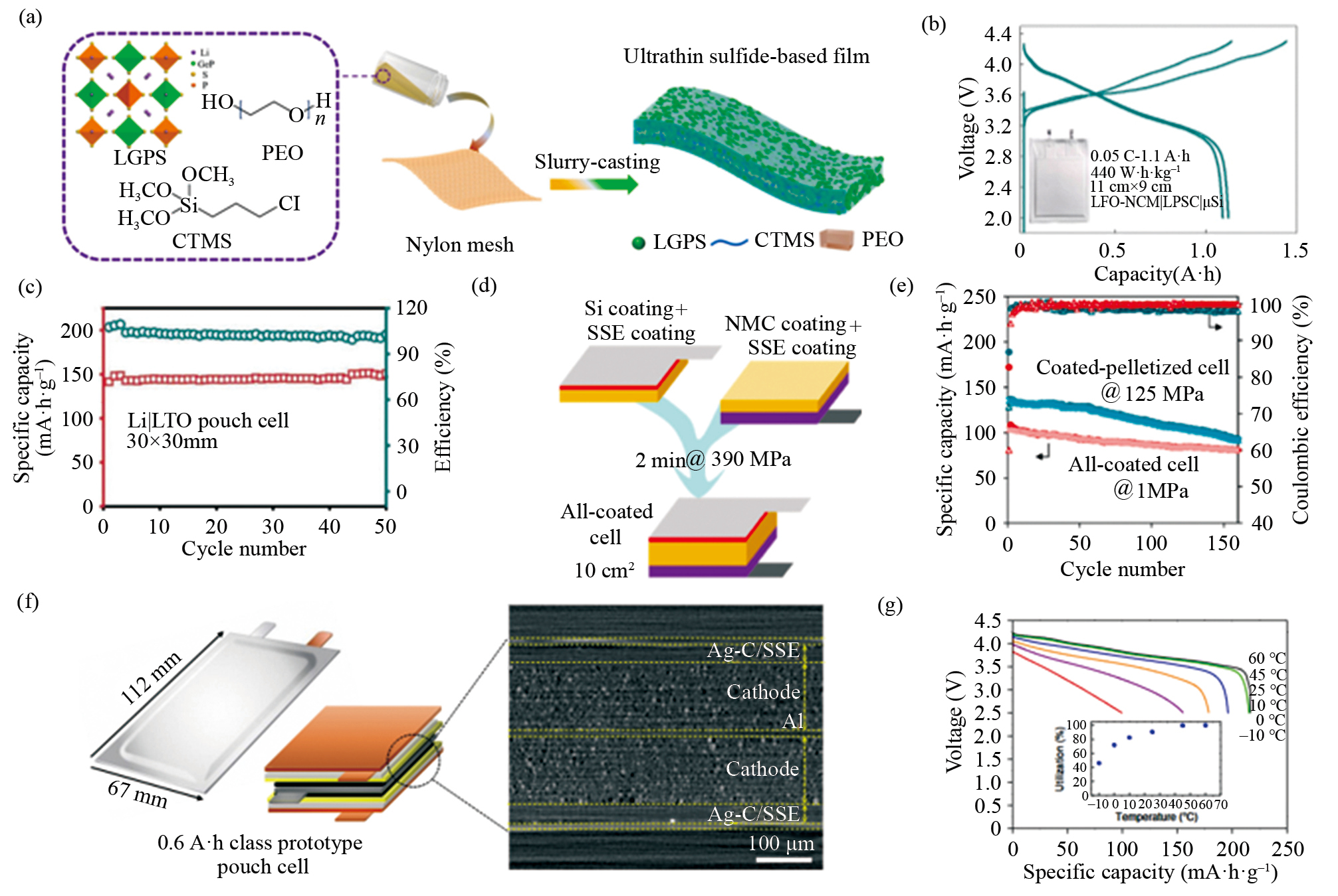
A fluorine-rich gel protective layer was applied to the lithium anode to suppress dendrite growth, enhancing the Coulombic efficiency and long-term cycling stability of the battery. The pouch battery demonstrated stable performance even under harsh conditions such as bending, cutting, and punching. To improve the compatibility of SSEs with high-voltage cathodes, Xu et al. [46] used NCM811 coated with LFO as the cathode material, achieving both prelithiation and suppression of NCM811 oxidation of SSEs. The assembled 1.1 A·h LFO-NCM811|LPSCI|Li-free Si pouch battery achieved an energy density of up to 440 W·h·kg–1 (Fig. 4(b)).
ASSBs using SSEs often need to apply extremely high stack pressures in order to ensure tight contact and mechanical stability of the interface. However, the complex and bulky pressurization devices, combined with the soft and ductile physical properties of lithium metal, significantly limit the practical use and commercialization of SSEs. Therefore, it is essential to explore methods for reducing stack pressure or replacing lithium metal with alternative anode materials. Zhu et al. [R3.2] prepared 60 μm ultrathin, self-supporting, flexible SSEs by coating Li6PS5Cl on a commercial cellulose (CEL) scaffold using a blade-coating technique. The assembled 30 mm × 30 mm TIO|Li pouch battery demonstrated a 100% capacity retention and 99% Coulombic efficiency after 50 cycles at 0.1 C under 5–10 kPa pressure (Fig. 4(c)). Grandjean et al. [48] selected nano-silicon (nSi), which has lower electrochemical activity, better mechanical properties, and is compatible with the slurry coating process, as the anode material. Using a double-casting process adapted to the standard LIBs production methods, they prepared a 16 mA·h NCM622|LPSCI|nSi pouch battery, which achieved 79% capacity retention after 160 cycles at C/20 with only 1 MPa operating pressure at room temperature (Fig. 4(d), (e)). Lee et al. [49] used a silver-carbon composite anode to construct a lithium-free anode and fabricated a 0.6 A·h high-nickel NCM|LPSCI|Ag-C pouch battery (Fig. 4(f)). Under 2–4 MPa stack pressure at 60 °C, the battery capacity retained 95% and 89% after 600 and 1000 cycles at 0.5 C, respectively. The authors also investigated the variation in discharge capacity at different temperatures. Compared to 60 °C, the discharge capacity at 45 °C was 99.5%, at 25 °C it dropped to 90.7%, and at –10°C, it was only 40% of the initial capacity (Fig. 4(g)). Thus, operating ASSBs at higher temperatures can enhance the performance and lifespan of EVs.
In conventional liquid LIBs, the theoretical capacity of graphite anodes (372 mA·h·g–1) no longer meets the goals of ASSBs, which aim for high specific capacity and energy density. Therefore, there is a need to explore new anode materials. Considering the technological maturity of various anode materials and their compatibility with large-scale commercial applications, options ranging from silicon-carbon anodes to lithium foils under 40 μm, and even lithium-free anode routes, have been proposed [39].
Silicon has a specific capacity (3590 mA·h·g–1 based on Li15Si4 at room temperature) that is approximately ten times that of graphite anodes [50], and its lithiation potential of 0.4 V (vs. Li+/Li) effectively prevents lithium plating and dendrite formation [51]. Additionally, silicon's abundant natural reserves and low cost make it a promising candidate for ASSBs. However, the significant volume change (>300%) during lithium intercalation and deintercalation causes silicon particles to continually crack and pulverize. The exposure of new active particle surfaces to the LEs environment leads to the continuous growth of an irreversible SEI layer, resulting in lithium loss, poor cycling performance, and low Coulombic efficiency [52]. In ASSBs, however, applying high stack pressure and using SEs with high mechanical strength can effectively mitigate the volume change effects of silicon and extend the battery's cycle life. Cangaz et al. [53] prepared one-dimensional (1D) columnar silicon (col-Si) anodes using physical vapor deposition (PVD) and assembled a high-nickel NCM|LPSCI|col-Si pouch battery with a nominal capacity of 8 mA·h. By applying pressures ranging from 1 MPa to 25 MPa, they found that as pressure increased, both the cycling performance and capacity retention improved (Fig. 5(b)). Furthermore, the authors demonstrated that when a certain stack pressure is applied to the battery pack, the battery's thickness and pressure signal undergo changes and plateaus during charge/discharge cycles, returning to the initial value after the cycle (Fig. 5(a)). This provides new insights into establishing a relationship between pressure and state of battery.
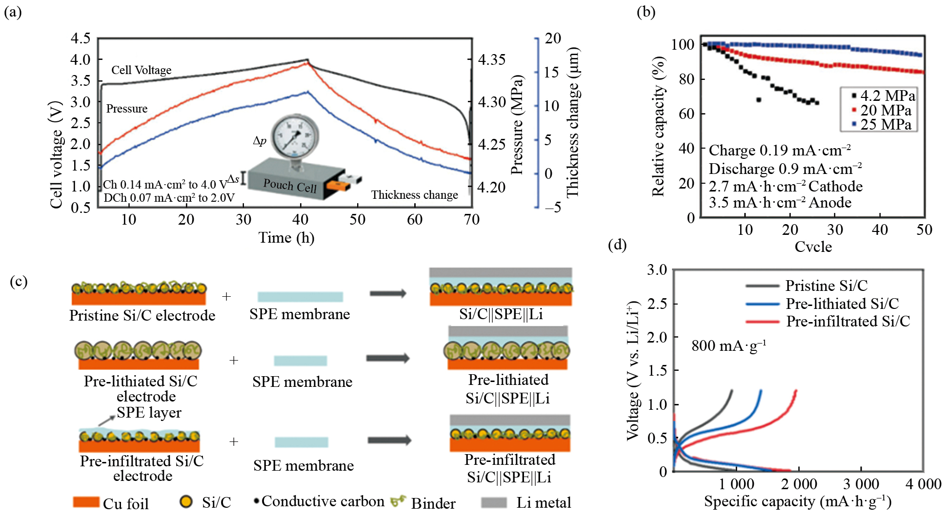
To alleviate the significant volume changes associated with pure silicon anodes and further enhance the anode's electronic conductivity [55], silicon-carbon composite materials have been developed. Carbon coating can effectively improve the stability of silicon, but the performance of silicon-carbon composite anodes often depends on factors such as the choice of carbon source, structural optimization, synthesis techniques, and processing methods [56]. Since the addition of carbon can cause the decomposition of SSEs [57], pairing silicon-carbon anodes with PSEs that offer better interfacial contact and stability is an effective approach to ensuring the stable operation of silicon-carbon anodes. Dong et al. [54] fabricated Si/C|PEO-LiTFSI|Li batteries using three types of micro-sized porous silicon-carbon anodes: pristine, prelithiated by liquid electrolyte, and preinfiltrated with polymer electrolyte (Figs. 5(c) and (d)). Test results showed that, at 60 °C, the mechanical stability of the PEO electrolyte plays a dominant role in the electrochemical performance of ASSBs, being more important than ionic conductivity.
Lithium metal has an extremely high theoretical capacity (3862 mA·h·g–1) and the lowest electrochemical redox potential (3.040 V vs. standard hydrogen electrode (SHE)). However, in ASSBs, due to electrochemical and safety constraints, the low critical current density of the lithium metal anode is prone to cause the growth of lithium dendrites and trigger the cracking of SEs, which restricts the high rate performance of the batteries and hinders the application of fast-charging technology. Additionally, issues such as side reactions at the electrode/electrolyte interface and infinite volume changes during cycling result in low lithium utilization, rapid capacity decay, and safety risks. Several scholars have provided detailed discussions on the main challenges, failure mechanisms, and improvement strategies for lithium metal anode pouch batteries [18, 58].
Anode-free ASSBs are made with a lithium-free bare collector placed at the anode, and lithium on the cathode side is deposited on the surface of the collector during charging to form an initial lithium anode, which implies that the negative-to-positive capacity ratio (N/P) is 0 [59]. Since there is no excess active lithium on the anode side, this design can effectively improve energy density, reduce production complexity, and enhance battery safety [60]. However, due to the lack of an additional lithium source to replenish the electrochemically active lithium lost during cycling, the battery experiences rapid capacity loss and poor cycling stability. Scholars have also systematically analyzed the design principles, key factors affecting cycling performance, and improvement strategies for anode-free lithium metal pouch batteries [59, 61].
The cathode active materials can be classified into intercalation compounds and conversion materials based on their state during the charge/discharge cycle [19]. In the former, lithium-ions are inserted and extracted in the active material structure to complete the storage and release of energy, while in the latter, the transformation of energy is achieved through the reaction between the active material and lithium-ions to generate other phases [62]. Conversion materials, such as sulfides, typically require the addition of large amounts of solid-state electrolytes and conductive additives due to their low ionic and electronic conductivity, which results in relatively low active material content. Issues such as the "shuttle effect" of sulfur, a narrow voltage window, poor interface compatibility, and significant volume changes currently limit the practical application of sulfur-based cathodes. Although most research is still at the laboratory stage, their ultra-high theoretical capacity (1675 mA·h·g–1) offers promising prospects for future applications [63].
Current intercalation compounds commonly used in LIBs cathodes such as olivine-type LFPs and layered NCMs can also be applied to ASSBs. LFP's stable structure and high safety make it an excellent candidate for quasi-solid-state batteries. However, the relatively low energy density of LFP (170 mA·h·g–1) will become more pronounced in ASSBs, where it will be crucial to further enhance the specific capacity and cut-off voltage of cathode active materials to improve the overall energy density. High-nickel materials (LiNi0.8Co0.1Mn0.1O2, LiNi0.90Co0.05Mn0.05O2) and lithium- and manganese-rich (LMR) layered structure cathodes are promising alternatives. As the nickel content increases, both the energy density and specific capacity of the cathodes improve. Additionally, reducing cobalt content helps lower material costs and facilitates the commercialization of these materials. However, excessively high nickel content can lead to the release of singlet oxygen at lower voltages [64] and cation disorder, which also reduces thermal stability. LMR cathodes (xLi2MnO3·(1−x)LiMO2, M = Ni, Co, Mn, or combinations) offer outstanding specific capacity (>300 mA·h·g–1) and good thermal stability, with thermal decomposition temperatures above 250 °C [65]. However, in practice LMR cathodes suffer from voltage decay, hysteresis, low first efficiency, poor multiplicity and cycling performance, etc. [66, 67]
In this section, we will comprehensively analyze the differences between ASSBs and traditional LIBs from 11 aspects: ionic conductivity, solid-solid interface contact, electrochemical window, operating temperature range, thermal safety, gases, lithium dendrite formation, internal short circuits, stacking technology, manufacturing consistency, and vibration shocks, which puts forward new demands and improvement directions for ASSBMS.
Considering the current technological maturity of various solid electrolytes (SEs), the most developed PSEs exhibit the lowest ionic conductivity. A low ionic conductivity leads to battery polarization, increased internal resistance, reduced cycle life and thermal stability. Therefore, PSEs need to be heated above glass transition temperature to reduce crystallinity and facilitate the effective migration of lithium ions.
In 2011, Bolloré Company attempted to use PSEs to manufacture solid-state batteries, which were then applied in EVs [68, 69]. The Bluecar, for example, is equipped with a 30 kW·h LFP|PEO|Li solid-state battery, achieving a driving range of 120 km. However, the operating temperature of the battery is 60–80 °C, which is higher than the optimal operating temperature range of traditional LIBs (15–35°C). This requires the battery to be heated above 60 °C before use in order to maintain its conductivity.
The ionic conductivity of inorganic solid-state electrolytes follows the Arrhenius equation, which shows an exponential increase with rising temperature [70, 71]. Therefore, raising the operating temperature of ASSBs is crucial for improving their cycle performance and energy efficiency. However, excessively high temperatures can degrade the stability of electrode active materials and the electrode/electrolyte interface, leading to side reactions and thermal decomposition, which compromises battery safety. This presents new demands and challenges for the temperature range control of all-solid-state battery thermal management systems (ASSBTMS) and the heating methods for ASSBs.
Unlike the full infiltration of LEs, poor solid-solid interface contact in ASSBs is a major factor limiting their commercialization [72]. During charge and discharge cycles, the significant volume changes of the cathode and anode lead to rapid degradation of interface contact, resulting in increased local current density, accelerated aging of the battery, and decreased safety performance [73]. Therefore, appropriate stack pressure needs to be applied during the operation of ASSBs.
In contrast to traditional lithium-ion batteries used in vehicles, which typically only require simple strap binding and fixation without the need for additional pressure, applying pressure in ASSBs requires careful design of pressurizing equipment and fixtures. This undoubtedly increases manufacturing costs and reduces the energy density of the battery pack. This is a significant disadvantage of ASSBs and presents new challenges for ASSBMS.
On one hand, it is necessary to determine the packaging form of the battery, the pressure application method, the arrangement of fixtures and flow channels, and the layout of pressure control harnesses. On the other hand, it is essential to develop all-solid-state battery pressure management system (ASSBPMS). This system must fully understand the volume change characteristics of the battery at different states of charge (SOC) during cyclic aging, as well as the compatibility of the electrode/electrolyte interface under various pressure conditions [74]. Real-time monitoring and adjustment of the applied stack pressure are crucial to ensure effective interface contact without compromising battery and material performance, improving cycle life and safety.
The use of lithium metal and high-voltage cathodes in ASSBs increases the cell voltage, thereby enhancing the battery's energy density. However, when traditional test methods are used, such as assembling Li|electrolyte|inert metal (Pt, Au) half-blocking electrodes and applying cyclic voltammetry (CV) to test the electrochemical window of the SEs, the reaction current is often exaggerated due to the limited contact area between the SEs and inert metal. This results in an overstated electrochemical stability window. Improper setting of the upper and lower cutoff voltages can lead to instability of the SEs or continuous side reactions at the electrode/electrolyte interface, which is unacceptable for on-board ASSBs that are required to undergo long cycle times.
There is a need for improvements in both testing devices and methods, or for computational approaches to assess the electrochemical stability window [75]. For example, Han et al. [43] demonstrated using an improved Hebb-Wagner battery configuration that the true thermodynamic stability window of LGPS is between 1.71–2.14 V, significantly narrower than the previously assumed 0–5 V. In practical applications, it is essential to consider various factors that can cause changes in the stable electrochemical window, such as passivation layers formed by interface side reactions, and the presence of grain boundaries and defects in the crystal structure, all of which can lead to shifts in the electrochemical window [76].
It is important to note that applying external pressure can effectively widen the stable electrochemical window. This is primarily due to phase transitions or changes in chemical composition, which cause volume changes. Under mechanical constraints, side reactions require additional energy to overcome the Gibbs free energy difference induced by the external pressure [77]. Therefore, to enhance the cutoff voltage and fully unlock the potential of ASSBs while maintaining efficient, stable, and long-term operation, the integration of ASSBPMS in the all-solid-state battery management system is essential.
The viscosity of LEs increases at low temperatures, and phenomena such as electrolyte crystallisation or localised solidification can occur, leading to a sudden drop in ionic conductivity and retardation of the chemical reaction at the electrode interface, which severely restricts the application of conventional LIBs in cold environments and is accompanied by safety risks. In comparison, solid electrolytes (SEs) exhibit exponential decay in ionic conductivity at low temperatures, which similarly degrades battery performance. However, SEs generally have better thermal stability at higher temperatures and can operate over a wider temperature range. For example, PSEs have a safe operating temperature range of 0–80 °C [78, 79], while SSEs can operate between –30°C and 100°C [42], and OSEs can potentially cover even broader ranges. A team in Japan demonstrated that an ASSBs using OSEs can cycle at 1C rate between –40 °C and 170 °C for 100 cycles without significant capacity degradation and apparent side reactions. This suggests that ASSBs have great potential for use in a wide range of operating environments, especially those encountered in transportation.
In contrast, the safe operating temperature range for traditional LIBs is typically –10 °C to 50 °C, with an ideal operating range of 20–30 °C. For every 1 °C increase in temperature, the battery's operational lifespan decreases by approximately 2 months [80], indicating the need for precise temperature control in ASSBTMS. In ASSBs, higher temperatures actually enhance the performance of SEs, meaning that the temperature lower limit can be set based on ionic conductivity requirements, and the upper limit can be determined by the stability requirements of the electrode materials. Whether the requirement of control accuracy can be reduced or not, it needs more actual test data of large-capacity batteries for judgement.
ASSBs are considered safer than traditional LIBs because they do not contain volatile organic esters that pose combustion and explosion risks. However, despite the lack of flammable solvents, ASSBs, as high-energy-density chemical energy storage devices with high-voltage cathodes and lithium metal anodes, do not possess intrinsic safety [81]. Thermal hazards, including exothermic reactions and thermal runaway, have been observed in batteries using PSEs, OSEs, and SSEs [82].
For example, Yang et al. [83]conducted thermal hazard testing on a 3.8 A·h NCM523|LPSCI|Li pouch battery using SSEs. The battery's self-heating temperature at 100% state of charge (SOC) (178.0 °C) and thermal runaway temperature (275.5 °C) were both higher than those of LIBs (112.2 °C and 215.3 °C, respectively). The maximum temperature of the battery (1210.7 °C) also exceeded that of LIBs (1148.4 °C). This indicates that while thermal runaway in ASSBs is harder to trigger, once it occurs, it releases significantly more heat. Similarly, Charbonnel et al. [84] reported that a battery made with OSEs, which have better thermal stability, demonstrated higher reaction speed and maximum temperature during thermal runaway than conventional liquid LIBs, even producing rare shockwaves that caused severe damage.
Several factors can contribute to heat generation and thermal runaway in ASSBs, such as lithium dendrites causing internal short circuits, deposition of products from interface side reactions, and decomposition reactions between water vapor and certain inorganic SEs that are sensitive to environmental conditions [85]. These phenomena can accumulate heat during the cycling process and trigger thermal runaway in ASSBs.
To mitigate these risks, it is crucial to eliminate thermal runaway triggers during electrode manufacturing, packaging, and monitoring processes. This includes developing higher-precision thermal models for ASSBs, advanced thermal management algorithms, and more robust tiered warning strategies. Furthermore, cooling methods and flow paths need to be carefully designed. In terms of flame-retardant materials, appropriate materials and layouts must be chosen to prevent the rapid spread of thermal runaway and reduce the harm and damage caused by explosions.
In summary, while the use of SEs in ASSBs reduces the risk of thermal runaway compared to LEs, it may increase the severity of thermal runaway events. Therefore, the early warning and buffering technologies for thermal runaway risks, as well as flame-retardant techniques, will become key focus areas for ASSBTMS in the development of ASSBs.
ASSBs can generate various reductive and toxic gases, such as H2, CH4, C2H6, and C2H4, during operation, which can reduce battery performance and safety [86]. Nie et al. [87] found that PSEs can be catalytically reduced by LCO at 4.2 V to produce H2, and Differential electrochemical mass spectrometry (DEMS) measurements also detected O2 generation. These potential side reactions and combustion risks pose serious safety hazards to the battery. Inorganic SEs are sensitive to air, and the garnet-type LLZO reacts easily with CO2 and H2O to form Li2CO3 and LiOH [88]. Additionally, SSEs can react with H2O to produce H2S gas [89], which reduces ion conductivity and increases interface resistance, impacting charging and discharging performance and Coulombic efficiency.
Gas accumulation can hinder the application of pressure, reducing the tight contact between the electrode and electrolyte interface, causing uneven distribution of local stress, and triggering further side reactions that accelerate battery aging. Therefore, it is crucial to ensure the proper sealing of pouch cells during operation and to design exhaust valve that effectively vent generated gases, extending the battery's cycle life and enhancing the safety of the battery pack.
Addressing the formation of lithium dendrites in ASSBs is one of the key technologies for enabling the use of lithium metal anodes. The electronic conductivity of SEs (10–9 S·cm–1) is significantly higher than that of traditional organic separators (10–15 to 10–16 S·cm–1). Han et al. [90] discovered through neutron diffraction spectroscopy (NDP) that the high electronic conductivity of SEs is one of the reasons for the formation of lithium dendrites. Kasemchainan et al. [91] found that when the stripping current density from the interface exceeds the deposition rate, lithium at the interface forms voids, which increases the local current density and leads to dendrite formation. By assembling symmetric Li|LPSCI|Li cells with SSEs and applying 3 MPa and 7 MPa pressures, they found that the maximum current densities without void and dendrite formation were 0.2 mA·cm–2 and 1.0 mA·cm–2, respectively. This indicates that controlling the current density and applying pressure can improve the battery's cycling stability.
Molecular dynamics (MD) simulations of Li+ transport in the alternating single-ion polymer electrolyte (alter-SIPE) reveal that the maximum distance lithium ions can travel is 0.21 nm, which is the ideal gap to inhibit dendrite growth in ASSBs [92]. However, internal pores in the electrode are typically in the range of tens to hundreds of nanometers, and significant volume changes during cycling make it difficult to maintain the electrode's compactness. Therefore, simply modifying the SEs and electrode/electrolyte interface using traditional material science techniques cannot fundamentally suppress dendrite formation. It is necessary to incorporate ASSBMS to monitor dendrite formation, control the applied current and voltage, and adjust the applied stack pressure in real-time. These measures can help suppress or slow down dendrite growth, reducing the performance degradation and safety risks associated with lithium dendrites.
Internal short circuits refer to direct electrical connections between the two electrodes within a battery, where current flows internally from one electrode to the other without passing through the external device. This leads to significant Joule heating and is a major cause of battery failure. PSEs may shrink, deform, or decompose at high temperatures [93], potentially causing direct contact between the cathode and anode, posing a risk of internal short circuits. The yield strength of submicron lithium dendrites can reach 244 MPa, which is much higher than that of 1 MPa for bulk lithium metal, so lithium dendrites piercing through the solid electrolyte is also one of the important reasons for the short circuit within ASSBs [94].
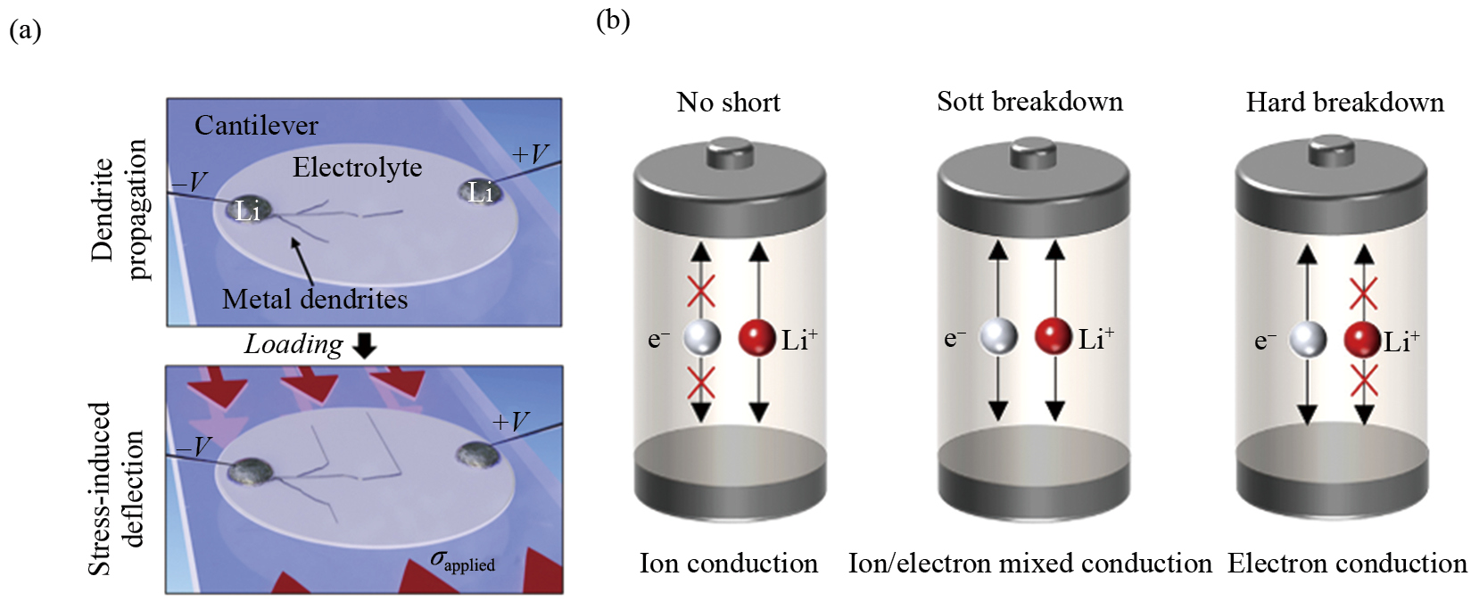
Ping et al. [95] found that lithium tends to deposit at the electronic conductive sites on the Li/OSEs interface and inside the garnet-type OSEs. By increasing the temperature to lower the ratio of electronic conductivity to ionic conductivity, the growth of lithium dendrites inside OSEs can be significantly suppressed. Fincher et al. [96] proposed that the growth of lithium dendrites is primarily caused by the plastic fracture of SEs. By applying mechanical loads, the actual stress direction of dendrite growth is influenced by the combined force of plating-induced pressure and stack pressure, which redirects the growth path and helps prevent internal short circuits in ASSBs to a certain extent (Fig. 6(a)).
Soft short circuits refer to small-scale, transient, and unstable electronic connections that can eventually evolve into permanent battery failures (Fig. 6(b)). Wang et al. [97] developed a simple and effective cyclic voltammetry method to diagnose soft breakdowns in all-solid-state symmetric cells. They also used low-frequency electrochemical impedance spectroscopy (EIS) to quantitatively analyze the degree of soft failure and established a standard testing protocol. Counihan et al. [98] used EIS to identify and quantify soft short circuits in ASSBs, based on the inverse relationship between the resistance of the electron and ion path as the temperature changes.
To reduce soft short circuits, it is effective to lower the current density and ensure that it does not exceed the critical current density. Therefore, from a management perspective, it is essential to combine electrical, thermal, and pressure monitoring techniques to detect and suppress internal short circuits in ASSBs, preventing the formation of dendrites or soft short circuits that could compromise battery performance and safety.
Unlike traditional LIBs, where individual cells are separately packaged, ASSBs use SEs that are non-flowing, allowing adjacent cells to share current collectors and packaging materials through stacking technology. This not only improves the energy and power density of the battery but also reduces manufacturing costs [99, 100]. ASSBs stacking technology can be divided into two types: bipolar stacking and parallel stacking. In bipolar stacking, each cell is connected in series through bipolar plates (BPs), while in parallel stacking, the tabs of each cell are connected to the current collector (CC), achieving parallel connection between cells (Fig. 7).
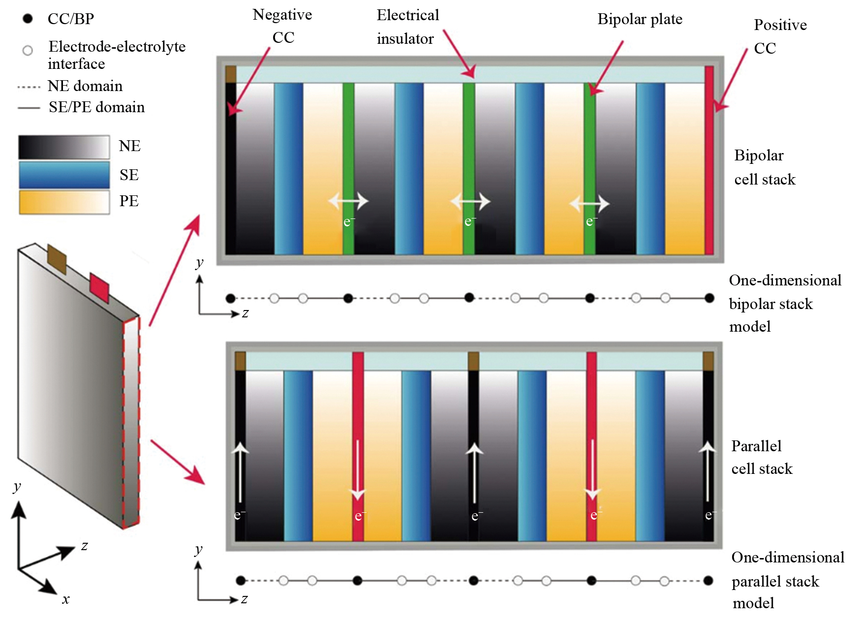
While a single-layer battery has a large specific surface area and the heat generated can be neglected, the heat generation problem becomes more prominent in stacked batteries and limits the performance of pouch cells. Pang et al. [101] demonstrated through an electrothermal coupling model that the Joule heating effect can be neglected in bipolar stacking, but it dominates in parallel stacking. Therefore, bipolar stacking is considered to have better application prospects as it reduces the cooling requirements of the ASSBTMS. This method has been validated in ASSBs using both PSEs and inorganic solid electrolytes, achieving higher voltage and energy density while demonstrating good cycle stability [102, 103].
However, bipolar stacking suffers from lower Coulombic efficiency and higher failure risks. Due to the series connection structure, when one cell fails, the entire pouch battery fails as well. Additionally, the BPs must contact both the anode and cathode, posing higher challenges for their chemical and electrochemical stability. From the material and manufacturing perspective, there is a need to develop bipolar plates that are resistant to oxidation and reduction, along with advanced stacking designs to avoid internal short circuits [104]. From management perspective, although the heat management requirements are reduced, there is still a need to explore how to apply uniform and stable pressure on multilayer pouch cells and how to analyze battery failure locations and causes based on aggregate battery monitoring data.
Due to the difficulty of achieving sufficient voltage and capacity from a single cell to meet the demands of EVs, multiple cells are often required to be connected in series and parallel. However, during the battery manufacturing process, small discrepancies among individual cells—resulting from factors such as materials, assembly, and environmental conditions—are inevitably amplified once the cells are assembled into a battery pack. Consequently, the overall performance of the battery pack, including its capacity, cycle life, and safety, often depends on the performance of the weakest cell.
In a series circuit, for example, the cell with the smallest capacity determines the module's total capacity, restricting the potential of the other cells. Cells with higher internal resistance will generate more Joule heat during charge and discharge cycles, accelerating their aging process and causing premature failure of the entire battery module [105].
Currently, the manufacturing precision of ASSBs is not yet mature, and ensuring uniform contact at the solid-solid interfaces is difficult. This leads to variations in internal resistance within the assembled battery. The "barrel effect" will therefore be more pronounced in ASSBs. Puls et al. [106] provided the same commercial materials to 21 different research groups, each using their own battery assembly protocol, while following the same electrochemical testing protocol. They found that different processing pressures and compression times during the assembly stage caused significant variations in the specific capacity, with the lowest charge capacity being 71 mA·h·g–1 and the highest reaching 195 mA·h·g–1. Such large capacity discrepancies are unacceptable in actual production. Therefore, from the formulation of materials to processing technology solutions should be controlled with strict precision to improve the consistency of the battery. At the ASSBMS level, in addition to balancing management, it is also necessary to screen and replace cells that deviate significantly from the overall performance to enhance the battery's service life and safety.
Onboard power batteries are often required to operate in vibrating environments. For traditional LIBs, vibrations can lead to increased DC internal resistance, active lithium loss, and the fracture and delamination of active materials, which quickly deteriorate the cycle performance [107]. In ASSBs, during the fabrication and assembly process, ultra-high pressure is applied to ensure effective solid-solid interface contact between the electrode materials and the battery pack. However, this effective interface may be compromised under vibration conditions. In the absence of the wetting effect of LEs, the separation or fracture of interfaces cannot be restored to initial state. Uneven current density and the formation of cracks will promote the growth of lithium dendrites, leading to rapid capacity loss and failure of the battery.
Additionally, the battery pack may also be exposed to collisions, gravel splashed during driving, drops, or scratches, etc., such a short period of strong external impact will cause the battery thermal runaway occurred [108]. Currently, ASSBs primarily use mechanical abuse tests, such as bending, shearing, and nail penetration, to demonstrate the safety of pouch cells [109, 110]. However, there is a lack of comprehensive performance and safety testing at the battery pack level, which is composed of multiple cells.
To facilitate the industrial application of ASSBs, it is essential to use both experimental and simulation methods to investigate the battery's response under different amplitudes, frequencies, and types of impacts [107]. Moreover, mechanical design of the battery pack should be reinforced. To mitigate the performance degradation of ASSBs, the battery pack should incorporate vibration isolation methods, such as using rubber pads or spring systems to reduce the vibration transmitted from the vehicle. The outer shell and internal brackets of the battery pack should be made of high-strength materials, such as aluminum alloys or composite materials, to increase structural rigidity, absorb vibrational energy, and minimize the impact on the battery cells [111, 112].
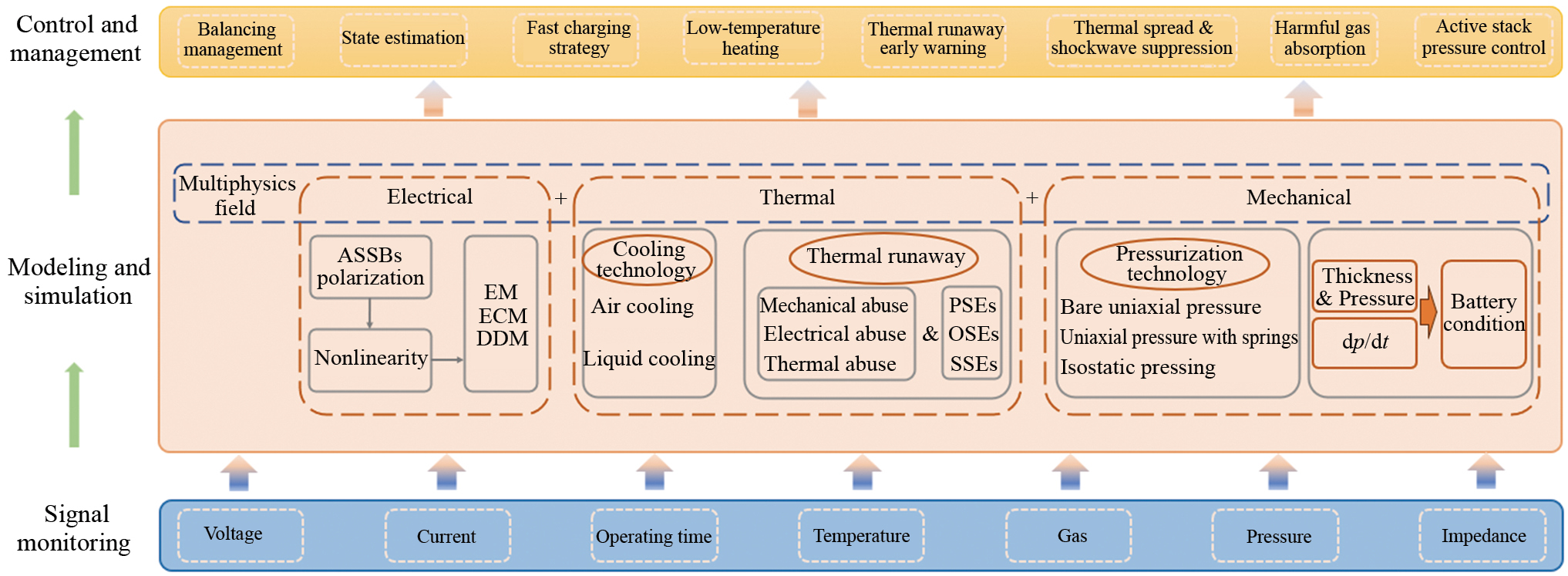
In this section, we will focus on the construction of ASSBMS tailored to the characteristics of ASSBs. Highlights what adjustments and improvements should be made to the traditional BMS architecture. At the management level, we innovatively propose that stacking pressure should be applied, monitored and adjusted for ASSBs. ASSBMS can be specifically divided into three parts: all-solid-state battery electric management system (ASSBEMS) describing the electrical characteristics, all-solid-state battery thermal management system (ASSBTMS) describing the temperature characteristics and all-solid-state battery pressure management system (ASSBPMS) describing the mechanical characteristics (Fig. 8).
In terms of sensor arrangement and signal sampling, traditional LIBs modules are made up of multiple large-capacity battery cells connected in series, requiring the analog front end (AFE) to sample and monitor the voltage of each individual cell [113]. In contrast, ASSBs use bipolar stacking technology, where multiple cells are packaged and connected in series within a single pouch, reducing the need for voltage sampling of each cell, complex circuit arrangements, and the balancing management between different cells. This design reduces the difficulty of simultaneous acquisition of multi-dimensional signals such as voltage and current. However, because pouch cells may have differing voltages, internal resistances, and capacities, these variations are further amplified after packing. Therefore, it is essential to enhance precision control during the manufacturing process to ensure the consistency of the pouch cell and meet higher standards of uniformity.
Battery models form the theoretical foundation for management algorithms and are crucial for understanding battery performance, predicting behavior, and optimizing management strategies. By establishing battery models, complex battery systems can be simplified into understandable mathematical expressions, providing a basis for the design, analysis, and optimization of battery management algorithms. Models can be categorized into electrochemical models (EM), equivalent circuit models (ECM), and data-driven models (DDM).
In EM, the pseudo-two-dimensional (P2D) electrochemical model proposed by Doyle et al. [114], which relies on concentrated solution theory for mass and charge conservation in the liquid phase, will no longer be applicable to ASSBs and needs modification or new models. For example, using the Nernst–Planck equation to describe the migration and diffusion dynamics of the electrolyte [115]. ECM simulates battery dynamic characteristics using components like resistors, capacitors, and voltage sources. For instance, the commonly used second-order RC equivalent circuit in algorithm development includes Ohmic resistance, electrochemical polarization, and concentration polarization, while the anion in single-ion conducting SPEs is fixed or constrained, forcing lithium ions to migrate to maintain charge neutrality, thus avoiding concentration polarization effects [116]. The topology of electronic components in ECM is typically fitted based on battery characteristics and then provided with electrochemical explanations, so various ECMs can still be applied in ASSBs, though their mechanistic explanations may need to be adjusted based on the properties of SEs. Firouz et al. [117]developed the Hammerstein-Wiener nonlinear model, which separates and identifies the linear and nonlinear components of the battery system using the best linear approximation (BLA) method and multi-sine excitation inputs. This model can detect, quantify, and simulate battery behavior and can also be used to detect potential faults at the electrode-electrolyte interface based on the nonlinear level of measured voltage. DDMs, which do not require understanding the internal structure of the battery, rely only on test data and intelligent algorithms to describe the highly nonlinear battery characteristics, making them easily applicable to ASSBs[118]. However, the scarcity of ASSB test data and complex calculations hinder the short-term economic application of DDMs.
Due to the low lithium-ion conductivity and solid-solid interface contact in ASSBs, polarization becomes more pronounced when current flows, exhibiting strong nonlinear characteristics. Researchers have studied state of charge (SOC) estimation to address these features. Kim et al. [119] developed a solid-state battery model based on a system of partial differential equations and used an Extended Kalman Filter (EKF) to estimate the SOC of solid-state batteries. By simultaneously considering the diffusion of both the cathode and electrolyte, the accuracy estimation in the low SOC range (0.1 < SOC < 0.4) was improved, reducing the error estimation to 5%. Deng et al. [120], to avoid linearizing the model using Taylor expansion and enhance its precision, employed the sigma-point Kalman filter (SPKF) for joint estimation of ASSB states and parameters. They performed sensitivity analyses on a large number of electrochemical parameters and identified online the maximum and minimum lithium ion concentrations of the parameters that have the greatest impact on the results. The results showed that under initial SOC, electrolyte concentration, and sensitive parameter errors, the average absolute errors for voltage and SOC estimation were below 2.1 mV and 1.5%, respectively. He et al. [121] developed a dual-layer stacked ensemble model using machine learning techniques. Random forest (RF), Gaussian process regression (GPR), and gradient boosting decision trees (GBDT) served as base models, with GBDT acting as the meta-model. This model enabled real-time SOC estimation for NCM622|PVDF-LLZTO|Li full solid-state batteries under various temperatures, achieving a Root Mean Square Error (RMSE) of 1.42%. However, the technological route and manufacturing precision for ASSBs still need to be determined and improved. Some of the technological methods are still in the experimental validation phase, and large-scale mass production has not yet been achieved. Therefore, long-cycle testing data for large-capacity ASSBs is still scarce, and corresponding State of Health (SOH) estimation methods are yet to be developed.
Generally, EVs that can charge within 0.5–2 hours are classified as fast-charging vehicles, while those that can charge in under 10 min are categorized as ultra-fast charging vehicles [122]. Fast charging technology significantly shortens charging times, enhancing the practicality and convenience of EVs and alleviating "range anxiety" [123]. However, several challenges hinder the application of fast-charging technology in ASSBs. These include the low ionic conductivity of SEs, uneven stripping and deposition of lithium on the lithium metal anode at high charge rates, the rapid and uneven migration of lithium from the NCM cathode, which increases internal stress and compromises structural stability, poor solid-solid interface contact, and significant volume changes.
To improve the fast-charging performance of batteries, advancements in materials and structural design are essential [124]. Additionally, optimizing the current and voltage applied during the charging process has been shown to effectively reduce temperature rise during fast charging, enhance charging efficiency, improve battery cycle life, and lower safety risks [125, 126]. In ASSBs, Zhu et al. [127] assembled a Li|LPS|LTO pouch cell using SSEs and demonstrated that by reducing the electrochemical window to 1.4–2.4 V, fast charge-discharge rates of up to 6 C could be achieved, with a capacity retention of 85% after 600 cycles at 1C. However, due to the lack of large-capacity ASSBs tested in real-world applications, further exploration and verification of optimization and control strategies for fast charging are still needed.
Like liquid LIBs, ASSBs also need to avoid operating in environments with low, high, or environments with temperature differences [128]. It is essential to select appropriate heat transfer mediums and implement effective thermal management strategies. Battery thermal management systems (BTMS) can be classified into four types: air cooling, liquid cooling, phase-change material cooling, and thermoelectric cooling [129]. Among these, air and liquid cooling systems are the most commonly used in EVs because they can be actively optimized based on the battery's thermal load [130].
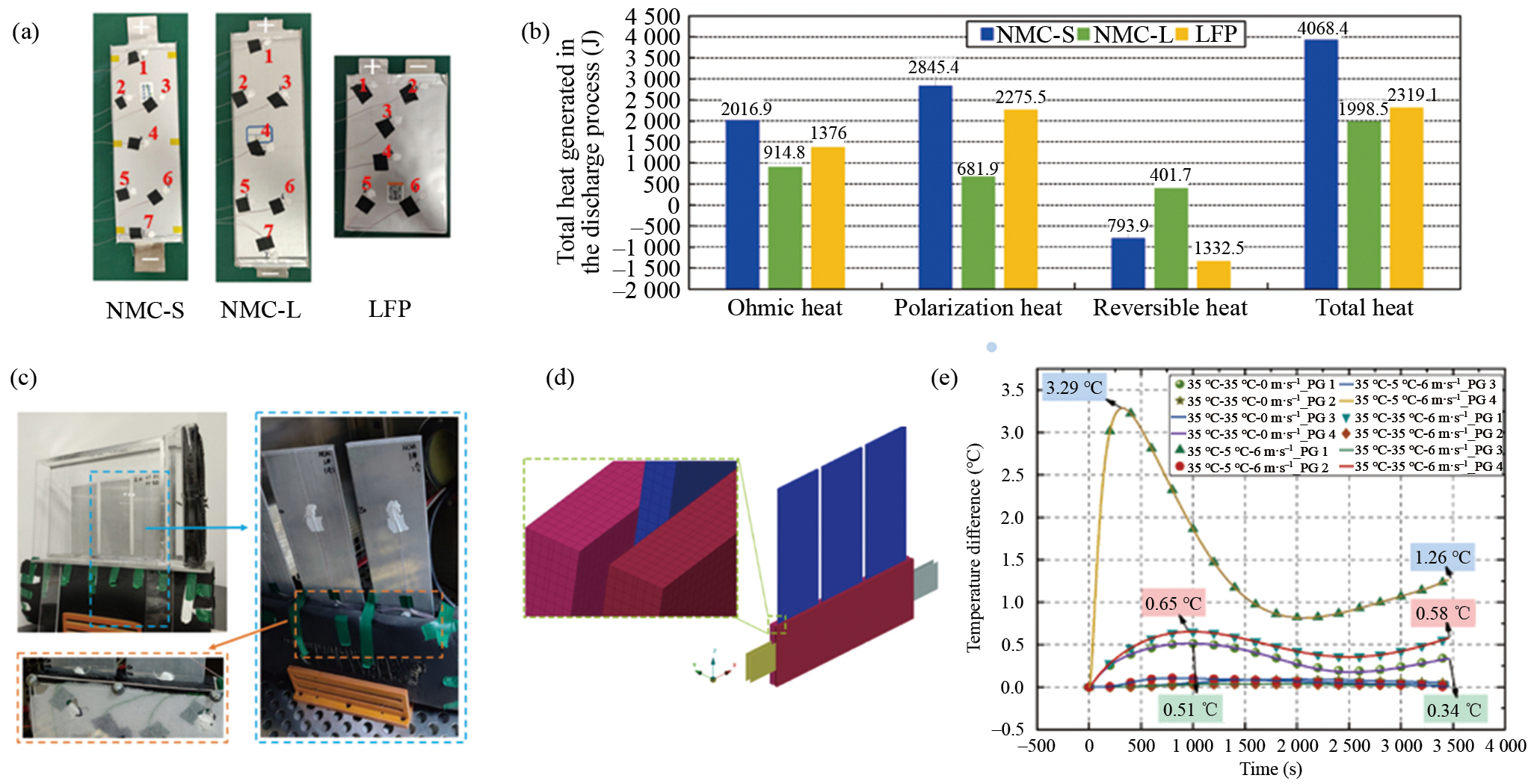
Yang et al. [131] compared the thermal characteristics of NCM quasi-solid batteries containing LLZO with traditional NCM and LFP liquid LIBs at different temperatures and current rates. The results showed that at different temperatures, SOC, and current densities, the polarization and ohmic resistance of quasi-solid-state batteries were higher than those of traditional NCM and LFP batteries (Fig. 9(a), (b)). This led to greater ohmic and polarization heat generation, and as the temperature decreased, the total heat produced during discharge increased, which places higher demands on the cooling capabilities of the ASSBTMS. This team also applied a hybrid ASSBTMS combining a micro heat pipe array (MHPA) and air cooling technology to a 21.3 A·h 2P1S NCM|LLZO|Gr battery pack, resulting in a temperature reduction of over 15 °C [132] (Fig. 9(c), (d)). However, stronger cooling capability could cause temperature gradients within the battery pack, leading to uneven current distribution and SOC inconsistency (Fig. 9(e)). Liquid cooling, however, can achieve higher heat transfer efficiency than air cooling at lower flow rates [129]. Direct cooling by immersing the batteries in a non-conducting dielectric fluid with a high specific heat capacity can maximize the cooling surface area and reduce the temperature difference between different battery modules, which is conducive to consistent performance and degradation of different batteries, and to improve the service time of the battery pack [69, 133]. Direct cooling technology can even be coupled with the ASSBPMS system to enhance the cycling performance of ASSBs. This architecture will be discussed in detail in the next section.
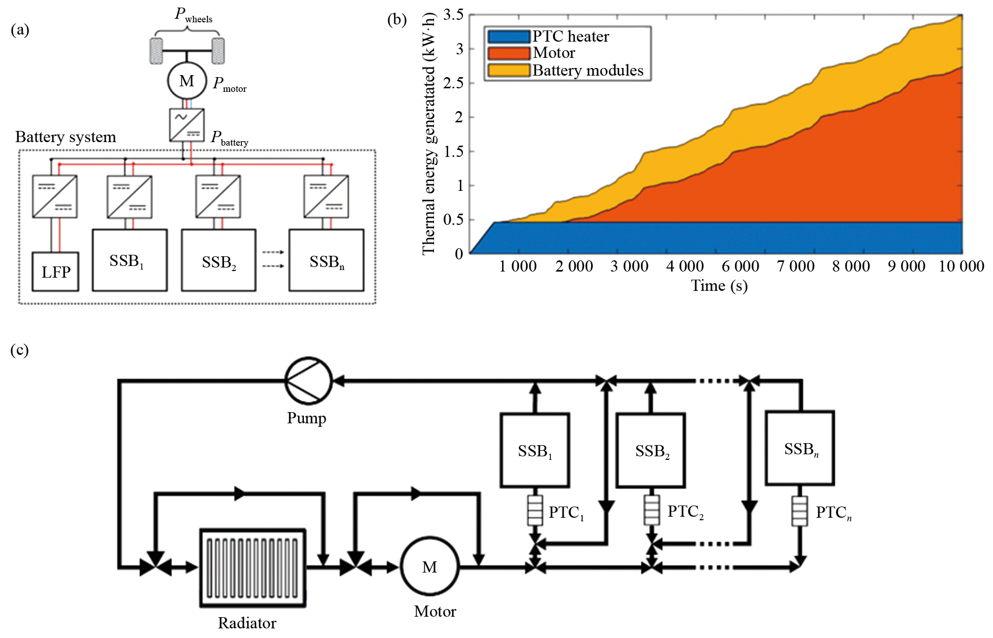
ASSBs typically require operation at higher temperatures (>60°C). Achieving cold start of ASSBs in vehicles at room or lower temperatures is crucial for their commercial viability. Hughes et al. [69] proposed a hybrid battery pack architecture that uses a small LFP battery to drive a Positive Temperature Coefficient (PTC) heater for initial heating and provide traction power (Fig. 10(a), (c)). Subsequent heating energy is gradually supplied by the preheated SPEs batteries and the waste heat generated during motor operation (Fig. 10(b)). Furthermore, the SPEs batteries are divided into thermally insulated and functionally independent submodules to enhance heating efficiency.
Although ASSBs are considered safer due to their higher self-heating and thermal runaway temperatures, higher maximum temperatures and the associated shockwave generation can lead to more significant damage. Therefore, ASSBs should pay more attention to how to effectively inhibit the generation of thermal runaway and stop the spread of thermal runaway. First, it is necessary to analyze the triggers and evolutionary mechanisms of thermal runaway.
Similar to traditional LIBs, the causes of thermal runaway in ASSBs can still be attributed to three main categories: mechanical abuse involving bending, cutting, and puncturing; electrical abuse such as overcharging, overdischarging, and internal short-circuiting; and thermal abuse in high-temperature environments [134]. ASSBs lack the separator components in liquid-based LIBs, which are typically the first to melt and thermally shrink during thermal runaway. The thermal runaway pathways and triggering mechanisms differ depending on the type of SEs used in the ASSBs[134] (Fig. 11(a)–(c)). PSEs-based ASSBs also involve polymer melting and thermal shrinkage at temperatures above 110 °C, which triggers internal short circuits and accelerates thermal runaway [135]. For ASSBs with SSEs, the thermal runaway mechanism varies based on material type and operating conditions. However, reactions between oxygen released during the thermal decomposition of oxide cathodes and SSEs are considered key factors in triggering thermal runaway [83]. In ASSBs using OSEs, the reaction between the lithium metal anode and the electrolyte may be the first step in triggering thermal runaway [81].
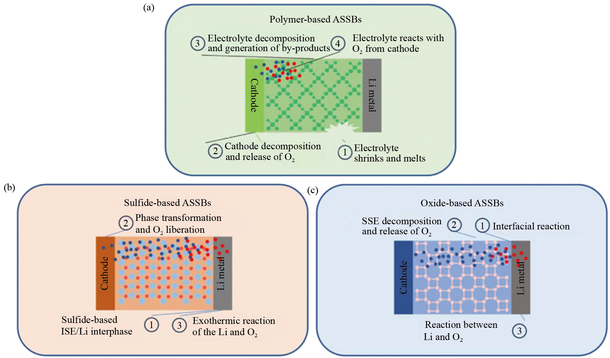
As a transitional technology from liquid-based LIBs to ASSBs, quasi-solid-state batteries are being studied. Chen et al. [82] systematically compared the thermal runaway behavior of custom-made quasi-solid electrolytes and LEs at four levels: electrolyte, electrolyte/electrode interface, coin cell, and pouch cell. Their experiments demonstrated that the use of quasi-solid electrolytes significantly raised the temperature at which reducing gases were generated, delaying the self-heating and onset of thermal runaway.
Simulating the uncontrollable chain reactions under extreme conditions of ASSBs through simulation methods can help predict and prevent catastrophic outcomes. Bates et al. [136] used a thermodynamic model to quantitatively evaluate the thermal release of LLZO quasi-solid-state batteries with different energy densities. The model compared these batteries to traditional LIBs under external heating, internal short circuit, and mechanical failure of OSEs. The study found that quasi-solid-state batteries only exhibited higher safety in scenarios of external heating failure. Additionally, the authors pointed out that while adding small amounts of LEs increased heat generation, the slight increase in heat generation was considered acceptable in terms of cost and practical commercial applications, especially since it helped reduce the interface resistance to one percent by interface wetting.
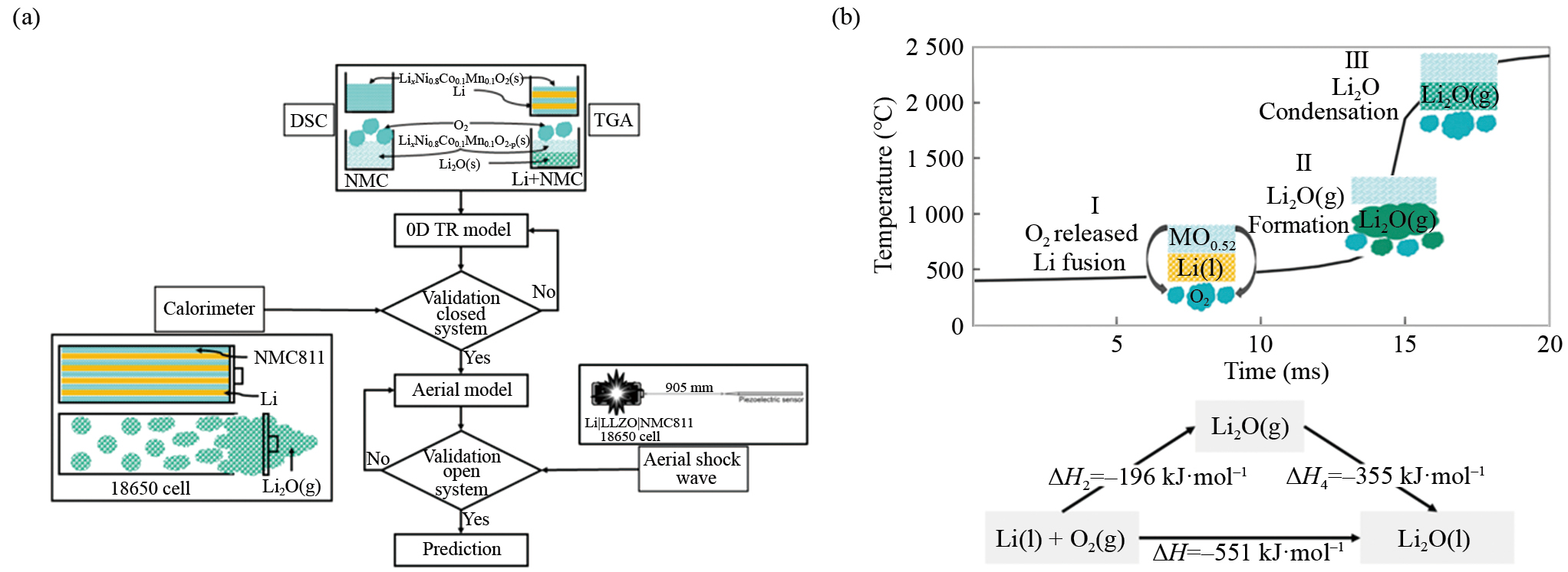
Juliette, et al. [137] constructed a 0-dimensional thermal runaway and explosion wave model, using thermogravimetric analysis (TGA) and differential scanning calorimetry (DSC) to determine the model parameters (Fig. 12(a)). The model predicted the thermal runaway behavior of Li|LLZO|NCM811 in a closed calorimeter, with results consistent with experimental data. The oxygen released from the cathode during thermal runaway and its intense reaction with lithium were found to be critical to the thermal behavior of ASSBs (Fig. 12(b)). The resulting gases eventually exceeded the pressure limit of the battery casing, causing it to rupture and forming a blast wave overpressure that could damage the surrounding structure. Charbonnel et al. [138] demonstrated the same by constructing a 2-D transient thermal model based on a large 60 A·h battery. The model simulated temperature changes of LCO|LLZO|Li batteries during thermal gradient testing and short-circuit conditions. They observed that due to the anisotropic thermal conductivity of the battery, the rate of thermal runaway propagation differed in different directions. The heat generated in the short-circuit region was enough to trigger thermal runaway across the entire battery.
Gas monitoring, as a method for early warning of battery aging and thermal runaway, has been widely studied in the LIBs [139, 140]. In ASSBs, gas monitoring can also play a crucial role in identifying early signs of thermal runaway or degradation. For example, the presence of oxygen (O2) in the expelled gases can indicate the decomposition of nickel-rich layered cathode materials. Meanwhile, monitoring sulfur dioxide (SO2) gas can signal the decomposition of SSEs due to gas-solid reactions, which are exothermic and can serve as a warning of thermal runaway [141]. In addition, harmful gases such as H2S, produced by side reactions in SSEs, could pose significant environmental and health risks in large-scale battery pack applications [142]. A gas absorption and conversion system should be deployed within the battery pack to efficiently handle harmful gas components [143, 144], ensuring the safety of vehicle occupants and reducing the complexity of emergency response in the event of an incident.
Suppressing the thermal spread and damage caused by shock waves in ASSBs is critically important. The application of direct cooling technology is expected to reduce the risks of thermal runaway and thermal spread, but it requires selecting dielectric coolants with high flash points and non-flammability to ensure that the cooling medium does not ignite when the battery undergoes thermal runaway and combustion. Li et al. [145] conducted heating tests with heating rods on commercial NCM batteries immersed in five different fluorocarbon-based coolants, none of which experienced thermal runaway. However, batteries using air cooling experienced thermal runaway at 145 ℃. This proves that direct cooling technology can more effectively suppress or avoid battery thermal runaway. Nonetheless, the performance of ASSBs in dielectric coolants still requires further testing. To reduce the harm caused by shock waves during thermal runaway, several measures can be taken: continuing the use of modular design structures within the battery pack to isolate and reduce the impact range of shockwaves; deploying materials such as metal foams, polymer-based composites, and shape memory alloys (SMA) inside the battery pack to absorb and attenuate shock wave energy, reducing the intensity of the shock wave during an explosion [146–148]and increase explosion-proof devices in key locations such as the chassis of electric vehicles.
ASSBs typically require the application of high pressure during both manufacturing and operation. The optimal manufacturing pressure ensures the highest ionic conductivity of SEs/electrodes, and the ideal stack pressure achieves the best performance of the battery [74]. Therefore, the application and adjustment of uniform, constant stack pressure via ASSBPMS are urgently needed in ASSBMS. Chen et al. [149] argue that BPMS is essential for high-energy lithium metal batteries designed for EV applications, as it helps suppress the large volume changes and lithium dendrite growth during cycling, providing evenly distributed pressure and controlling the cycling process within the optimal pressure range to improve the battery's performance and safety.
On the one hand, low stack pressure fails to ensure tight contact between interfaces during cycling, reducing battery performance. On the other hand, excessively high stack pressure can lead to uneven stress distribution within the pouch cells, causing electrode and SEs particle cracking, current collector deformation, lithium metal micro-extrusion, and short-circuiting issues [150–152]. Moreover, high pressure puts higher demands on the pressurization equipment, increases system weight, reduces energy density, and raises manufacturing costs. Therefore, it is necessary to develop low-pressure battery designs supported by appropriate pressurization devices and pressure regulation management systems.
Traditional pouch battery holders consist of bolts, nuts, and rigid plates, which can apply uniaxial pressure to the pouch battery (Fig. 13(a)). However, due to the volume changes during ASSBs cycling, the cycling pressure also varies [153]. Incorporating springs and washers in the holders allows stacking pressure to be applied uniformly to the cell surface and accommodates volume changes during cycling [154] (Fig. 13(b)). Adjusting the pressure requires motors to overcome high friction under the load to rotate the bolts, and precisely control the torque to ensure uniform pressure application. This imposes stringent requirements on the ASSBPMS system [155].
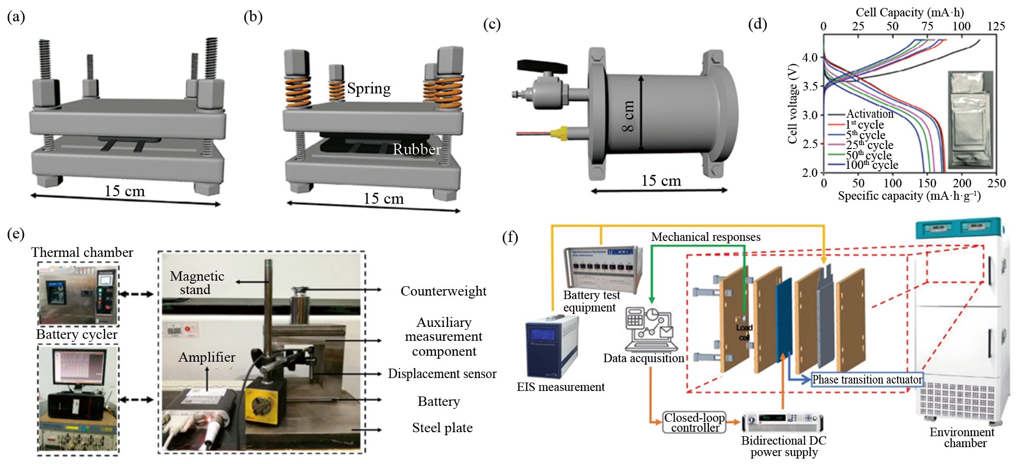
Isostatic pressure technology involves placing the battery in a high-pressure-resistant pressure vessel, where fluid media such as liquids or gases apply uniform, constant pressure in all directions over an extended period. This ensures effective contact between the electrode/electrolyte interface during cycling. Chen et al. [155] developed an iso-static pressure pouch battery holder with air as the pressurizing medium (Fig. 13(c)). For a NCM811|LPSCI|Si pouch battery with a theoretical capacity of 100 mA·h, a 2 MPa pressure was applied, resulting in a capacity retention rate of 83.6% after 100 cycles at 0.2 C (Fig. 13(d)). This reduced the requirements for cycling pressure and temperature, and compared to improved uniaxial pressure holders, it increased both the battery's capacity retention and energy density.
To determine the impact of stack pressure on the cycling performance of batteries and identify the appropriate pressure range, it is essential to couple the pressure field into the ASSBs models for adjustment. Gu et al. [158] developed a temperature-pressure-electrochemical coupling model for NCM811|LPSCI|Li@In batteries, identifying the optimal pressure range for the battery as 127.38–254.76 MPa. Simulation results showed that by applying suitable external pressure, the battery could improve discharge specific capacity, capacity retention, and suppress temperature rise. Jun et al. [159] developed a new operando differential electrochemical pressiometry (DEP) technique for ASSBs, constructing a correspondence between time- (or capacity-) derivative differential pressure (dP/dt or dP/dQ), which reflects the corresponding volume changes of the anode active materials, and SOC. Additionally, in situ DEP analysis could potentially diagnose failures such as lithium dendrite penetration through SEs or interface reactions between Li and SEs. Jiang et al. [156] built an equivalent mechanical model considering stack pressure. By measuring stack pressure, accurate battery thickness signals were obtained to estimate SOC, creating a new method for battery state estimation using force signals (Fig. 13(e)). This approach holds promising application potential for ASSBs that require stack pressure during operation, helping improve the accuracy of state estimation.
ASSBPMS can be divided into passive and active pressure management. Passive pressure management is commonly used in battery formation, where the initial stack pressure cannot be adjusted during subsequent cycles or under different temperature conditions. Jeong et al. [157] proposed a new active pressure management framework, which uses a closed-loop control method and NCM batteries as phase-change actuators to precisely control their charge and discharge states, counteracting the volume changes target LIBs during charge and discharge cycles, maintaining stable internal pressure(Fig. 13(f)). Under the US06 driving conditions, the accumulated stress in the LIBs decreased by 56.7%, and the discharge capacity increased by 1.4% compared to passive pressure control. This approach provides a reference for active pressure management in ASSBs.
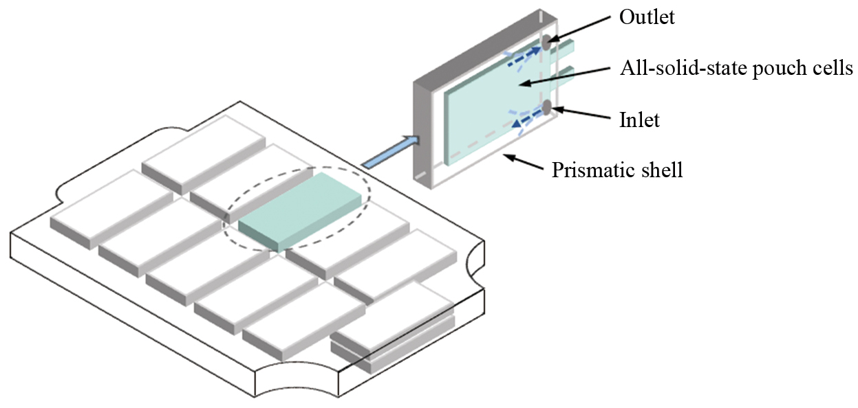
We propose a next-generation battery architecture based on the ASSBs' packaging form, direct immersion cooling thermal management technology, and active pressure management strategies (Fig. 14). The ASSBs pouch batteries are constructed by bipolar stacking technology, encapsulated in lightweight high-strength prismatic shells, with low-temperature-resistant, non-flammable dielectric fluids as the cooling and pressurisation medium, which can effectively dissipate the heat of the ASSBs as well as exert a uniform isostatic pressure on them. However, this approach may have some challenges: (1) The introduction of the prismatic shells and dielectric fluid requires reassessment of whether the energy density of the ASSBs meets the requirements of the intended application scenarios. (2) Due to the high specific heat capacity of the liquid, a higher energy consumption and longer time may be required to heat the dielectric fluid during cold starts. (3) How to optimally set the liquid inlet and outlet to achieve a more uniform temperature gradient. (4) Energy consumption for maintaining isostatic pressure needs to be evaluated, and whether a pressure retention device should be installed during shutdown to ensure that the battery remains under high pressure to maintain effective interface contact.
During the cycling process of ASSBs, effectively monitoring interface impedance using EIS and formulating corresponding regulation strategies can significantly extend the battery's lifespan. Krauskopf et al. [160] found that with increasing external pressure, the interface resistance between the lithium metal anode and LLZO decreased. When subjected to several hundred megapascals of external pressure, the interface resistance could even approach 0 Ω·cm². Zhang et al. [161] conducted EIS testing on LCO|LGPS|In cells at different charge and discharge stages to obtain Nyquist plots. The results indicated that during charging, the cathode interface resistance in the mid-frequency range increased due to cathode volume changes, breakdown of the protective layer on the cathode surface, and decomposition of the SSEs. During discharge, as the Li/In molar ratio decreased, the anode interface resistance in the low-frequency range increased. Therefore, based on EIS monitoring, a graded pressurization strategy can be developed according to the different states of the battery pack. This strategy can ensure the tight contact between the solid-solid interfaces without damaging the electrode and electrolyte materials.
In summary, we have provided a comprehensive overview of how to construct ASSBMS tailored to the characteristics of ASSBs to accelerate their industrial application. On the material front, we discussed the advantages and disadvantages of polymer, oxide, and sulfide-baced solid electrolytes, as well as promising candidates for high-energy-density anodes and cathodes. To overcome the drawbacks in electrode and electrolyte materials, we presented advancements in battery materials and design, highlighting improvements in cycling and safety performance for pouch cell configurations.
From the demand side, we detailed the differences between ASSBs and traditional liquid LIBs across 11 dimensions, emphasizing the specific requirements and concerns for battery management in practical applications. On the supply side, we focused on the differences between ASSBMS and traditional BMS, introducing the necessary adjustments and improvements to existing BMS architectures across three dimensions: electrical, thermal, and pressure. In particular, the ASSBPMS needed to address the solid-solid interface contact characteristics was emphasized.
Although significant progress has been made by researchers in managing certain characteristics of ASSBs, there is still a lack of a systematic framework to integrate and validate these efforts. The following are key issues that future solid-state battery and management technology developments should address.
(1) The feasibility of fabricating and evaluating large-capacity ASSBs to meet the demands of practical application scenarios needs to be explored. Currently, many researchers tend to use small-scale molded batteries to test the performance of solid-state batteries in order to achieve better results. They often use lower-capacity pouch cells to demonstrate safety under mechanical abuse conditions, but this may differ from the degradation and failure mechanisms observed in large-capacity pouch cells used in real-world applications. To fabricate large-capacity ASSBs, key design parameters such as the electrode slurry formulation, SEs membrane thickness, and the number of stacking layers must be determined through advanced parameterization methods based on energy density requirements [162]. Additionally, preparation and assembly processes for SEs membranes suitable for mass production must be developed to align with existing LIBs manufacturing lines, minimizing the time and cost required for additional investments in production lines [163]. A cost-benefit analysis of the SEs manufacturing process is also necessary to drive commercialization and improve market competitiveness [164]. Finally, by standardizing the production of ASSBs, the compatibility between manufacturing processes and system management can be enhanced, promoting efficient scaling and market adoption.
(2) The scarcity of test data for ASSBs hinders the development of reliable predictive models and management systems. As the focus of ASSBs is still on the development of advanced materials, there are significant variations in assembly, electrochemical testing protocols, testing temperatures, manufacturing, and stacking pressures. These differences result in diverse cycling performance and failure mechanisms, making it difficult to extract common characteristics and build reliable predictive models through simple methods. This challenge can be addressed by obtaining large-capacity ASSBs with high consistency and systematically testing their performance under different operating conditions, temperatures, and pressure conditions. Such comprehensive testing will help reveal the physical and chemical processes involved in ion transport, interfacial reactions, stress evolution, etc., and define the boundary conditions for battery cycling. This data will be crucial for developing more accurate predictive models and improving management systems for ASSBs.
(3) Machine learning (ML) methods can be fully utilized to predict the development of ASSBs and enhance battery management performance. During the battery development phase, integrating experimental or simulation data into an ML framework can effectively assist in material screening, structural optimization, and performance prediction of SEs. This approach can improve the compatibility of electrode/electrolyte interfaces, reduce lithium dendrite growth, and promote the development of advanced SEs [165, 166]. In the battery management phase, ML algorithms can effectively predict the cycle life of ASSBs, and also have great application prospects in the subsequent batch classification, echelon utilisation and recycling of ASSBs [162]. However, under the condition of limited test data, the accuracy and reliability of these algorithms still require further validation.
(4) The coupling of multiple physical fields enhances the accuracy and safety of ASSBMS. The transition from traditional liquid LIBs to ASSBs introduces challenges in battery research and management due to the strong coupling between different physical and chemical fields [167]. To improve the state estimation accuracy of ASSBs and adjust the applied external temperature and pressure, it is necessary to develop a multi-physical field coupling model and management techniques that involve electrical, thermal, and mechanical interactions [168]. Additionally, methods such as EIS and gas monitoring can be used to monitor and provide early warnings for various battery failure modes. It is crucial to establish correlations between multi-physical measurement signals and battery aging or failure mechanisms, and to develop control strategies and graded warning strategies. However, this undoubtedly needs to improve the multi-dimensional signal synchronous sampling capability, increase the complexity of the control strategy and chip computing, resulting in a rise in the production cost of battery packs. Therefore, in practical applications, it is essential to balance control accuracy, safety, and cost, and to conduct a system evaluation of the feasibility for automotive applications.
To accelerate the transition of ASSBs and corresponding management technologies from laboratory research to market applications, interdisciplinary collaboration across materials science, (electro)chemistry, mechanical engineering, control systems, and artificial intelligence is essential to address the key challenges facing ASSBs and ASSBMS. We are confident that the analysis and insights presented in this review will provide valuable references for researchers, fostering rapid advancements in related fields.
This research was funded by the National Natural Science Foundation of China (NSFC, Nos. 52377211, 52107230, U20A20310, and 52176199) and the Fundamental Research Funds for the Central Universities. Xiaodong Wu gratefully acknowledge the financial support from the National Key R&D Program of China (No. 2022YFE0207300). Jiangong Zhu gratefully acknowledge the financial support from National Engineering Research Center of New Energy Vehicles and Power Systems and Shanghai Key Lab of Vehicle Aerodynamics and Vehicle Thermal Management Systems.
C. P. Grey and D. S. Hall, "Prospects for lithium-ion batteries and beyond-a 2030 vision," Nature Communications, vol. 11, no. 1, p. 6279, 2020.
J. Xie and Y. C. Lu, "A retrospective on lithium-ion batteries," Nature Communications, vol. 11, no. 1, p. 2499, 2020.
A. Masias, J. Marcicki, and W. A. Paxton, "Opportunities and challenges of lithium ion batteries in automotive applications," ACS Energy Letters, vol. 6, no. 2, pp. 621–630, 2021.
F. H. Gandoman, J. Jaguemont, S. Goutam, R. Gopalakrishnan, Y. Firouz, T. Kalogiannis, N. Omar, and J. Van Mierlo, "Concept of reliability and safety assessment of lithium-ion batteries in electric vehicles: Basics, progress, and challenges," Applied Energy, vol. 251, p. 113343, 2019.
R. Kumar and V. Goel, "A study on thermal management system of lithium-ion batteries for electrical vehicles: A critical review," Journal of Energy Storage, vol. 71, p. 108025, 2023.
M. H. Wu, S. H. Han, S. M. Liu, J. Q. Zhao, and W. Q. Xie, "Fire-safe polymer electrolyte strategies for lithium batteries," Energy Storage Materials, vol. 66, p. 103174, 2024.
S. Kainat, J. Anwer, A. Hamid, N. Gull, and S. M. Khan, "Electrolytes in lithium-ion batteries: Advancements in the era of twenties (2020's)," Materials Chemistry and Physics, vol. 313, p. 128796, 2024.
M. H. Zhang, M. Chouchane, S. A. Shojaee, B. Winiarski, Z. Liu, L. T. Li, R. Pelapur, A. Shodiev, W. L. Yao, J. M. Doux, S. Wang, Y. X. Li, C. Y. Liu, H. Lemmens, A. A. Franco, and Y. S. Meng, "Coupling of multiscale imaging analysis and computational modeling for understanding thick cathode degradation mechanisms," Joule, vol. 7, no. 1, pp. 201–220, 2023.
S. J. Yang, J. K. Hu, F. N. Jiang, H. Yuan, H. S. Park, and J. Q. Huang, "Safer solid-state lithium metal batteries: Mechanisms and strategies," Infomat, vol. 6, no. 2, p. e12512, 2024.
L. N. Jia, J. H. Zhu, X. Zhang, B. J. Guo, Y. B. Du, and X. D. Zhuang, "Li-solid electrolyte interfaces/interphases in all-solid-state Li batteries," Electrochemical Energy Reviews, vol. 7, no. 1, p. 20, 2024.
C. W. Wang, Y. H. Gong, J. Q. Dai, L. Zhang, H. Xie, G. Pastel, B. Y. Liu, E. Wachsman, H. Wang, and L. B. Hu, "In Situ neutron depth profiling of lithium metal-garnet interfaces for solid state batteries," Journal of the American Chemical Society, vol. 139, no. 40, pp. 14257–14264, 2017.
W. Lee, J. Lee, T. Yu, H.-J. Kim, M. K. Kim, S. Jang, J. Kim, Y. -J. Han, S. Choi, S. Choi, T. -H. Kim, S. -H. Park, W. Jin, G. Song, D. -H. Seo, S. -K. Jung, and J. Kim, "Advanced parametrization for the production of high-energy solid-state lithium pouch cells containing polymer electrolytes," Nature Communications, vol. 15, no. 1, p. 5860, 2024.
S. J. Liu, Y. Zhao, X. H. Li, J. Y. Yu, J. H. Yan, and B. Ding, "Solid-state lithium metal batteries with extended cycling enabled by dynamic adaptive solid-state interfaces," Advanced Materials, vol. 33, no. 12, p. 2008084, 2021.
Y. R. Xiao, K. Turcheniuk, A. Narla, A. Y. Song, X. L. Ren, A. Magasinski, A. Jain, S. Huang, H. Lee, and G. Yushin, "Electrolyte melt infiltration for scalable manufacturing of inorganic all-solid-state lithium-ion batteries," Nature Materials, vol. 20, no. 7, p. 984, 2021.
W. Zaman and K. B. Hatzell, "Processing and manufacturing of next generation lithium-based all solid-state batteries," Current Opinion in Solid State & Materials Science, vol. 26, no. 4, p. 101003, 2022.
J. Liu, Z. N. Bao, Y. Cui, E. J. Dufek, J. B. Goodenough, P. Khalifah, Q. Y. Li, B. Y. Liaw, P. Liu, A. Manthiram, Y. S. Meng, V. R. Subramanian, M. F. Toney, V. V. Viswanathan, M. S. Whittingham, J. Xiao, W. Xu, J. H. Yang, X. Q. Yang, and J. G. Zhang, "Pathways for practical high-energy long-cycling lithium metal batteries," Nature Energy, vol. 4, no. 3, pp. 180–186, 2019.
P. Shi, X. B. Cheng, T. Li, R. Zhang, H. Liu, C. Yan, X. Q. Zhang, J. Q. Huang, and Q. Zhang, "Electrochemical diagram of an ultrathin lithium metal anode in pouch cells," Advanced Materials, vol. 31, no. 37, p. 1902785, 2019.
H. Liu, X. Sun, X. B. Cheng, C. Guo, F. Yu, W. Z. Bao, T. Wang, J. F. Li, and Q. Zhang, "Working principles of lithium metal anode in pouch cells," Advanced Energy Materials, vol. 12, no. 47, p. 2202518, 2022.
S. Y. Wang, S. Liu, W. Chen, Y. Hu, D. J. Chen, M. He, M. J. Zhou, T. Y. Lei, Y. G. Zhang, and J. Xiong, "Designing reliable cathode system for high-performance inorganic solid-state pouch cells," Advanced Science, vol. 11, no. 23, p. 2401889, 2024.
S. Sen, E. Trevisanello, E. Niemöller, B. X. Shi, F. J. Simon, and F. H. Richter, "The role of polymers in lithium solid-state batteries with inorganic solid electrolytes," Journal of Materials Chemistry A, vol. 9, no. 35, pp. 18701–18732, 2021.
H. H. Xu, P. H. Chien, J. J. Shi, Y. T. Li, N. Wu, Y. Y. Liu, Y. Y. Hu, and J. B. Goodenough, "High-performance all-solid-state batteries enabled by salt bonding to perovskite in poly(ethylene oxide)," Proceedings of the National Academy of Sciences of the United States of America, vol. 116, no. 38, pp. 18815–18821, 2019.
M. J. Wu, J. P. Song, J. H. Lei, and H. L. Tang, "An artificial interphase enables stable PVDF-based solid-state Li metal batteries," Nano Research, vol. 17, no. 3, pp. 1482–1490, 2024.
D. Guo, D. B. Shinde, W. Shin, E. Abou-Hamad, A. H. Emwas, Z. P. Lai, and A. Manthiram, "Foldable solid-state batteries enabled by electrolyte mediation in covalent organic frameworks," Advanced Materials, vol. 34, no. 23, p. 2201410, 2022.
A. Du, H. T. Lu, S. S. Liu, S. Y. Chen, Z. H. Chen, W. H. Li, J. W. Song, Q. H. Yang, and C. P. Yang, "Breaking the trade-off between ionic conductivity and mechanical strength in solid polymer electrolytes for high-performance solid lithium batteries," Advanced Energy Materials, vol. 14, no. 31, p. 2400808, 2024.
X. Y. Ban, W. Q. Zhang, N. Chen, and C. W. Sun, "A high-performance and durable poly(ethylene oxide)-based composite solid electrolyte for all solid-state lithium battery," Journal of Physical Chemistry C, vol. 122, no. 18, pp. 9852–9858, 2018.
J. Schnell, T. Günther, T. Knoche, C. Vieider, L. Köhler, A. Just, M. Keller, S. Passerini, and G. Reinhart, "All-solid-state lithium-ion and lithium metal batteries—paving the way to large-scale production," Journal of Power Sources, vol. 382, pp. 160–175, 2018.
Q. W. Lu, C. H. Wang, D. N. Bao, H. Duan, F. P. Zhao, K. Doyle-Davis, Q. Zhang, R. N. Wang, S. Q. Zhao, J. T. Wang, H. Huang, and X. L. Sun, "High-performance quasi-solid-state pouch cells enabled by in situ solidification of a novel polymer electrolyte," Energy & Environmental Materials, vol. 6, no. 4, p. e12447, 2023.
N. X. Zhang, A. Beutl, K. Rajinovic, J. Kahr, M. Jahn, and M. Nestoridi, "Scalable preparation of practical 1Ah all-solid-state lithium-ion batteries cells and their abuse tests," Journal of Energy Storage, vol. 59, p. 106547, 2023.
C. Z. Zhao, B. C. Zhao, C. Yan, X. Q. Zhang, J. Q. Huang, Y. F. Mo, X. X. Xu, H. Li, and Q. Zhang, "Liquid phase therapy to solid electrolyte-electrode interface in solid-state Li metal batteries: A review," Energy Storage Materials, vol. 24, pp. 75–84, 2020.
P. Hartmann, T. Leichtweiss, M. R. Busche, M. Schneider, M. Reich, J. Sann, P. Adelhelm, and J. Janek, "Degradation of NASICON-Type materials in contact with lithium metal: Formation of mixed conducting interphases (MCI) on solid electrolytes," Journal of Physical Chemistry C, vol. 117, no. 41, pp. 21064–21074, 2013.
Q. Zhang, J. J. Zhou, P. Cui, Z. Y. Wang, P. Lv, K. H. Yu, and W. Wei, "Thin film oxide solid electrolytes towards high energy density batteries: progress of preparation methods and interface optimization," Journal of Materials Chemistry A, vol. 11, no. 28, pp. 15122–15139, 2023.
J. S. Kim, G. Yoon, S. Kim, S. Sugata, N. Yashiro, S. Suzuki, M. J. Lee, R. Kim, M. Badding, Z. Song, J. M. Chang, and D. Im, "Surface engineering of inorganic solid-state electrolytes via interlayers strategy for developing long-cycling quasi-all-solid-state lithium batteries," Nature Communications, vol. 14, no. 1, p. 782, 2023.
Y. Y. Ren, Y. Shen, Y. H. Lin, and C. W. Nan, "Direct observation of lithium dendrites inside garnet-type lithium-ion solid electrolyte," Electrochemistry Communications, vol. 57, pp. 27–30, 2015.
X. F. Yang, K. R. Adair, X. J. Gao, and X. L. Sun, "Recent advances and perspectives on thin electrolytes for high-energy-density solid-state lithium batteries," Energy & Environmental Science, vol. 14, no. 2, pp. 643–671, 2021.
R. Murugan, V. Thangadurai, and W. Weppner, "Fast lithium ion conduction in garnet-type Li7La3Zr2O12," Angewandte Chemie-International Edition, vol. 46, no. 41, pp. 7778–7781, 2007.
T. Thieu, E. Fedeli, O. Garcia-Calvo, I. Combarro, J. Nicolas, I. Urdampilleta, and A. Kvasha, "Long cycle-life prototype lithium-metal all-solid-state pouch cells employing garnet-rich composite electrolyte," Electrochimica Acta, vol. 397, p. 139249, 2021.
Z. Zhang, J. R. Gou, K. X. Cui, X. Zhang, Y. J. Yao, S. Q. Wang, and H. H. Wang, "12.6 μm-thick asymmetric composite electrolyte with superior interfacial stability for solid-state lithium-metal batteries," Nano-Micro Letters, vol. 16, no. 1, p. 181, 2024.
F. P. McGrogan, T. Swamy, S. R. Bishop, E. Eggleton, L. Porz, X. W. Chen, Y. M. Chiang, and K. J. Van Vliet, "Compliant yet brittle mechanical behavior of Li2S-P2S5 lithium-ion-conducting solid electrolyte," Advanced Energy Materials, vol. 7, no. 12, p. 1602011, 2017.
C. H. Wang, J. W. Liang, Y. Zhao, M. T. Zheng, X. N. Li, and X. L. Sun, "All-solid-state lithium batteries enabled by sulfide electrolytes: From fundamental research to practical engineering design," Energy & Environmental Science, vol. 14, no. 5, pp. 2577–2619, 2021.
R. Kanno and M. Maruyama, "Lithium ionic conductor thio-LISICON: The Li2S-GeS2-P2S5 system," Journal of the Electrochemical Society, vol. 148, no. 7, pp. A742–A746, 2001.
W. D. Jung, J. S. Kim, S. Choi, S. Kim, M. Jeon, H. G. Jung, K. Y. Chung, J. H. Lee, B. K. Kim, J. H. Lee, and H. Kim, "Superionic halogen-rich li-argyrodites using in situ nanocrystal nucleation and rapid crystal growth," Nano Letters, vol. 20, no. 4, pp. 2303–2309, 2020.
Y. Kato, S. Hori, T. Saito, K. Suzuki, M. Hirayama, A. Mitsui, M. Yonemura, H. Iba, and R. Kanno, "High-power all-solid-state batteries using sulfide superionic conductors," Nature Energy, vol. 1, p. 16030, 2016.
F. D. Han, Y. Z. Zhu, X. F. He, Y. F. Mo, and C. S. Wang, "Electrochemical stability of Li10GeP2S12 and Li7La3Zr2O12 solid electrolytes," Advanced Energy Materials, vol. 6, no. 8, p. 9, 2016.
J. Haruyama, K. Sodeyama, L. Y. Han, K. Takada, and Y. Tateyama, "Space-charge layer effect at interface between oxide cathode and sulfide electrolyte in all-solid-state lithium-ion battery," Chemistry of Materials, vol. 26, no. 14, pp. 4248–4255, 2014.
H. Liu, P. G. He, G. X. Wang, Y. H. Liang, C. Wang, and L. Z. Fan, "Thin, flexible sulfide-based electrolyte film and its interface engineering for high performance solid-state lithium metal batteries," Chemical Engineering Journal, vol. 430, p. 132991, 2022.
X. Q. Xu, S. Y. Chu, S. Xu, H. Y. Li, C. C. Sheng, M. X. Dong, S. H. Guo, and H. S. Zhou, "Integrating prelithiation and interface protection to achieve high-energy all-solid-state batteries," Angewandte Chemie-International Edition, p. e202415891, 2024.
G. L. Zhu, C. Z. Zhao, H. J. Peng, H. Yuan, J. K. Hu, H. X. Nan, Y. Lu, X. Y. Liu, J. Q. Huang, C. A. X. He, J. Zhang, and Q. Zhang, "A self-limited free-standing sulfide electrolyte thin film for all-solid-state lithium metal batteries," Advanced Functional Materials, vol. 31, no. 32, p. 2101985, 2021.
M. Grandjean, M. Perrey, X. Randrema, J. Laurier, P. Chenevier, C. Haon, and S. Liatard, "Low pressure cycling of solid state Li-ion pouch cells based on NMC-Sulfide-nanosilicon chemistry," Journal of Power Sources, vol. 585, p. 233646, 2023.
Y. G. Lee, S. Fujiki, C. H. Jung, N. Suzuki, N. Yashiro, R. Omoda, D. S. Ko, T. Shiratsuchi, T. Sugimoto, S. Ryu, J. H. Ku, T. Watanabe, Y. Park, Y. Aihara, D. Im, and I. T. Han, "High-energy long-cycling all-solid-state lithium metal batteries enabled by silver-carbon composite anodes," Nature Energy, vol. 5, no. 4, pp. 348–348, 2020.
A. Mukanova, A. Jetybayeva, S. T. Myung, S. S. Kim, and Z. Bakenov, "A mini-review on the development of Si-based thin film anodes for Li-ion batteries," Materials Today Energy, vol. 9, pp. 49–66, 2018.
A. F. Gonzalez, N. H. Yang, and R. S. Liu, "Silicon anode design for lithium-ion batteries: Progress and perspectives," Journal of Physical Chemistry C, vol. 121, no. 50, pp. 27775–27787, 2017.
Y. Yang, W. Yuan, W. Q. Kang, Y. T. Ye, Q. Q. Pan, X. Q. Zhang, Y. Z. Ke, C. Wang, Z. Q. Qiu, and Y. Tang, "A review on silicon nanowire-based anodes for next-generation high-performance lithium-ion batteries from a material-based perspective," Sustainable Energy & Fuels, vol. 4, no. 4, pp. 1577–1594, 2020.
S. Cangaz, F. Hippauf, F. S. Reuter, S. Doerfler, T. Abendroth, H. Althues, and S. Kaskel, "Enabling high-energy solid-state batteries with stable anode interphase by the use of columnar silicon anodes," Advanced Energy Materials, vol. 10, no. 34, p. 2001320, 2020.
P. P. Dong, Y. H. Cha, X. H. Zhang, J. Zamora, and M. K. Song, "Poly(ethylene) oxide electrolytes for all-solid-state lithium batteries using microsized silicon/carbon anodes with enhanced rate capability and cyclability," ACS Applied Materials & Interfaces, vol. 16, no. 31, pp. 41018–41026, 2024.
M. Ko, S. Chae, S. Jeong, P. Oh, and J. Cho, "Elastic a-silicon nanoparticle backboned graphene hybrid as a self-compacting anode for high-rate lithium ion batteries," ACS Nano, vol. 8, no. 8, pp. 8591–8599, 2014.
Q. Y. Man, Y. L. An, C. K. Liu, H. T. Shen, S. L. Xiong, and J. K. Feng, "Interfacial design of silicon/carbon anodes for rechargeable batteries: A review," Journal of Energy Chemistry, vol. 76, pp. 576–600, 2023.
D. H. S. Tan, Y. T. Chen, H. D. Yang, W. Bao, B. Sreenarayanan, J. M. Doux, W. K. Li, B. Y. Lu, S. Y. Ham, B. Sayahpour, J. Scharf, E. A. Wu, G. Deysher, H. E. Han, H. J. Hah, H. Jeong, J. B. Lee, Z. Chen, and Y. S. Meng, "Carbon-free high-loading silicon anodes enabled by sulfide solid electrolytes," Science, vol. 373, no. 6562, p. 1494, 2021.
Y. L. Jie, C. Tang, Y. L. Xu, Y. Z. Guo, W. X. Li, Y. W. Chen, H. J. Jia, J. Zhang, M. Yang, R. G. Cao, Y. H. Lu, J. P. Cho, and S. H. Jiao, "Progress and perspectives on the development of pouch-type lithium metal batteries," Angewandte Chemie-International Edition, vol. 63, no. 7, p. e202307802, 2024.
W. Z. Huang, C. Z. Zhao, P. Wu, H. Yuan, W. E. Feng, Z. Y. Liu, Y. Lu, S. Sun, Z. H. Fu, J. K. Hu, S. J. Yang, J. Q. Huang, and Q. Zhang, "Anode-free solid-state lithium batteries: A review," Advanced Energy Materials, vol. 12, no. 26, p. 2201044, 2022.
A. J. Louli, A. Eldesoky, R. Weber, M. Genovese, M. Coon, J. deGooyer, Z. Deng, R. T. White, J. Lee, T. Rodgers, R. Petibon, S. Hy, S. J. H. Cheng, and J. R. Dahn, "Diagnosing and correcting anode-free cell failure via electrolyte and morphological analysis," Nature Energy, vol. 5, no. 9, pp. 693–702, 2020.
L. W. Dong, S. J. Zhong, S. H. Zhang, B. T. Yuan, J. P. Liu, H. D. Xie, C. M. Zhang, Y. P. Liu, C. H. Yang, J. C. Han, and W. D. He, "Toward practical anode-free lithium pouch batteries," Energy & Environmental Science, vol. 16, no. 12, pp. 5605–5632, 2023.
S. Q. Xu, C. Y. Kwok, L. D. Zhou, Z. Z. Zhang, I. Kochetkov, and L. F. Nazar, "A high capacity all solid-state li-sulfur battery enabled by conversion-intercalation hybrid cathode architecture," Advanced Functional Materials, vol. 31, no. 2, p. 2004239, 2021.
B. B. Gicha, L. T. Tufa, N. Nwaji, X. J. Hu, and J. Lee, "Advances in all-solid-state lithium-sulfur batteries for commercialization," Nano-Micro Letters, vol. 16, no. 1, p. 172, 2024.
J. Wandt, A. T. S. Freiberg, A. Ogrodnik, and H. A. Gasteiger, "Singlet oxygen evolution from layered transition metal oxide cathode materials and its implications for lithium-ion batteries," Materials Today, vol. 21, no. 8, pp. 825–833, 2018.
H. X. Deng, I. Belharouak, Y. K. Sun, and K. Amine, "LixNi0.25Mn0.75Oy (0.5 ≤ x ≤ 2, 2 ≤ y ≤ 2.75) compounds for high-energy lithium-ion batteries," Journal of Materials Chemistry, vol. 19, no. 26, pp. 4510–4516, 2009.
J. M. Zheng, S. J. Myeong, W. R. Cho, P. F. Yan, J. Xiao, C. M. Wang, J. Cho, and J. G. Zhang, "Li- and Mn-rich cathode materials: Challenges to commercialization," Advanced Energy Materials, vol. 7, no. 6, p. 1601284, 2017.
T. Teufl, D. Pritzl, S. Solchenbach, H. A. Gasteiger, and M. A. Mendez, "State of charge dependent resistance build-up in Li- and Mn-rich layered oxides during lithium extraction and insertion," Journal of the Electrochemical Society, vol. 166, no. 6, pp. A1275–A1284, 2019.
C. Li, Z. Y. Wang, Z. J. He, Y. J. Li, J. Mao, K. H. Dai, C. Yan, and J. C. Zheng, "An advance review of solid-state battery: Challenges, progress and prospects," Sustainable Materials and Technologies, vol. 29, p. e00297, 2021.
R. Hughes and C. Vagg, "Assessing the feasibility of a cold start procedure for solid state batteries in automotive applications," Batteries-Basel, vol. 8, no. 2, p. 13, 2022.
N. Kamaya, K. Homma, Y. Yamakawa, M. Hirayama, R. Kanno, M. Yonemura, T. Kamiyama, Y. Kato, S. Hama, K. Kawamoto, and A. Mitsui, "A lithium superionic conductor," Nature Materials, vol. 10, no. 9, pp. 682–686, 2011.
F. Mizuno, A. Hayashi, K. Tadanaga, and M. Tatsumisago, "High lithium ion conducting glass-ceramics in the system Li2S-P2S5," Solid State Ionics, vol. 177, no. 26–32, pp. 2721–2725, 2006.
S. Jian, H. D. Li, X. B. Jia, D. L. Zhong, B. R. Tao, X. He, G. F. Wang, and H. X. Chang, "Interface engineering in LGPS-type solid-state electrolytes for all-solid-state lithium batteries," Flatchem, vol. 46, p. 100693, 2024.
K. J. Kim, M. Balaish, M. Wadaguchi, L. P. Kong, and J. L. M. Rupp, "Solid-state li-metal batteries: Challenges and horizons of oxide and sulfide solid electrolytes and their interfaces," Advanced Energy Materials, vol. 11, no. 1, p. 2002689, 2021.
X. Hu, Z. J. Zhang, X. Zhang, Y. Wang, X. Yang, X. Wang, M. Fayena-Greenstein, H. A. Yehezkel, S. Langford, D. Zhou, B. H. Li, G. X. Wang, and D. Aurbach, "External-pressure-electrochemistry coupling in solid-state lithium metal batteries," Nature Reviews Materials, vol. 9, no. 5, pp. 305–320, 2024.
T. Binninger, A. Marcolongo, M. Mottet, V. Weber, and T. Laino, "Comparison of computational methods for the electrochemical stability window of solid-state electrolyte materials," Journal of Materials Chemistry A, vol. 8, no. 3, pp. 1347–1359, 2020.
Y. Z. Zhu, X. F. He, and Y. F. Mo, "Origin of outstanding stability in the lithium solid electrolyte materials: Insights from thermodynamic analyses based on first-principles calculations," ACS Applied Materials & Interfaces, vol. 7, no. 42, pp. 23685–23693, 2015.
E. Gil-González, L. H. Ye, Y. C. Wang, Z. Shadike, Z. M. Xu, E. Y. Hu, and X. Li, "Synergistic effects of chlorine substitution in sulfide electrolyte solid state batteries," Energy Storage Materials, vol. 45, pp. 484–493, 2022.
Y. H. Li, X. L. Wu, J. H. Kim, S. Xin, J. Su, Y. Yan, J. S. Lee, and Y. G. Guo, "A novel polymer electrolyte with improved high-temperature-tolerance up to 170 °C for high-temperature lithium-ion batteries," Journal of Power Sources, vol. 244, pp. 234–239, 2013.
M. T. F. Rodrigues, G. Babu, H. Gullapalli, K. Kalaga, F. N. Sayed, K. Kato, J. Joyner, and P. M. Ajayan, "A materials perspective on Li-ion batteries at extreme temperatures," Nature Energy, vol. 2, no. 8, p. 17108, 2017.
B. Shabani and M. Biju, "Theoretical modelling methods for thermal management of batteries," Energies, vol. 8, no. 9, pp. 10153–10177, 2015.
R. S. Chen, A. M. Nolan, J. Z. Lu, J. Y. Wang, X. Q. Yu, Y. F. Mo, L. Q. Chen, X. J. Huang, and H. Li, "The thermal stability of lithium solid electrolytes with metallic lithium," Joule, vol. 4, no. 4, pp. 812–821, 2020.
S. Y. Chen, Q. K. Peng, Z. S. Wei, Y. X. Li, Y. B. Yue, Y. Zhang, W. Zeng, K. Q. Jin, L. H. Jiang, and Q. S. Wang, "Revealing the quasi-solid-state electrolyte role on the thermal runaway behavior of lithium metal battery," Energy Storage Materials, vol. 70, p. 103481, 2024.
S. J. Yang, J. K. Hu, F. N. Jiang, X. B. Cheng, S. Sun, H. J. Hsu, D. S. Ren, C. Z. Zhao, H. Yuan, M. G. Ouyang, L. Z. Fan, J. Q. Huang, and Q. Zhang, "Oxygen-induced thermal runaway mechanisms of Ah-level solid-state lithium metal pouch cells," Etransportation, vol. 18, p. 100279, 2023.
J. Charbonnel, S. Dubourg, E. Testard, L. Broche, C. Magnier, T. Rochard, D. Marteau, P. X. Thivel, and R. Vincent, "Preliminary study of all-solid-state batteries: Evaluation of blast formation during the thermal runaway," Iscience, vol. 26, no. 11, p. 108078, 2023.
Y. Luo, Z. H. Rao, X. F. Yang, C. H. Wang, X. L. Sun, and X. F. Li, "Safety concerns in solid-state lithium batteries: From materials to devices," Energy & Environmental Science, vol. 17, no. 20, pp. 7543–7565, 2024.
H. Y. Huo, K. Huang, W. Luo, J. T. Meng, L. Y. Zhou, Z. Deng, J. Y. Wen, Y. M. Dai, Z. M. Huang, Y. Shen, X. X. Guo, X. L. Ji, and Y. H. Huang, "Evaluating interfacial stability in solid-state pouch cells via ultrasonic imaging," ACS Energy Letters, vol. 7, no. 2, pp. 650–658, 2022.
K. H. Nie, X. L. Wang, J. L. Qiu, Y. Wang, Q. Yang, J. J. Xu, X. Q. Yu, H. Li, X. J. Huang, and L. Q. Chen, "Increasing poly(ethylene oxide) stability to 4.5 V by surface coating of the cathode," ACS Energy Letters, vol. 5, no. 3, pp. 826–832, 2020.
A. Sharafi, S. H. Yu, M. Naguib, M. Lee, C. Ma, H. M. Meyer, J. Nanda, M. F. Chi, D. J. Siegel, and J. Sakamoto, "Impact of air exposure and surface chemistry on Li-Li7La3Zr2O12 interfacial resistance," Journal of Materials Chemistry A, vol. 5, no. 26, pp. 13475–13487, 2017.
Y. Nikodimos, C. J. Huang, B. W. Taklu, W. N. Su, and B. J. Hwang, "Chemical stability of sulfide solid-state electrolytes: Stability toward humid air and compatibility with solvents and binders," Energy & Environmental Science, vol. 15, no. 3, pp. 991–1033, 2022.
F. D. Han, A. S. Westover, J. Yue, X. L. Fan, F. Wang, M. F. Chi, D. N. Leonard, N. Dudney, H. Wang, and C. S. Wang, "High electronic conductivity as the origin of lithium dendrite formation within solid electrolytes," Nature Energy, vol. 4, no. 3, pp. 187–196, 2019.
J. Kasemchainan, S. Zekoll, D. S. Jolly, Z. Y. Ning, G. O. Hartley, J. Marrow, and P. G. Bruce, "Critical stripping current leads to dendrite formation on plating in lithium anode solid electrolyte cells," Nature Materials, vol. 18, no. 10, p. 1105, 2019.
S. T. Han, P. Wen, H. J. Wang, Y. Zhou, Y. Gu, L. Zhang, Y. Shao-Horn, X. R. Lin, and M. Chen, "Sequencing polymers to enable solid-state lithium batteries," Nature Materials, vol. 22, no. 12, p. 1515, 2023.
L. Hu, X. Gao, H. Wang, Y. Song, Y. L. Zhu, Z. J. Tao, B. Yuan, and R. Z. Hu, "Progress of polymer electrolytes worked in solid-state lithium batteries for wide-temperature application," Small, vol. 20, no. 31, p. 2312251, 2024.
L. Q. Zhang, T. T. Yang, C. C. Du, Q. N. Liu, Y. S. Tang, J. Zhao, B. L. Wang, T. W. Chen, Y. Sun, P. Jia, et al., "Lithium whisker growth and stress generation in an in situ atomic force microscope-environmental transmission electron microscope set-up," Nature Nanotechnology, vol. 15, no. 2, p. 94, 2020.
W. W. Ping, C. W. Wang, Z. W. Lin, E. Hitz, C. P. Yang, H. Wang, and L. B. Hu, "Reversible short-circuit behaviors in garnet-based solid-state batteries," Advanced Energy Materials, vol. 10, no. 25, p. 2000702, 2020.
C. D. Fincher, C. E. Athanasiou, C. Gilgenbach, M. Wang, B. W. Sheldon, W. C. Carter, and Y. M. Chiang, "Controlling dendrite propagation in solid-state batteries with engineered stress," Joule, vol. 6, no. 12, pp. 2794–2809, 2022.
C. H. Wang, T. Deng, X. L. Fan, M. Zheng, R. Z. Yu, Q. W. Lu, H. Duan, H. Huang, C. S. Wang, and X. L. Sun, "Identifying soft breakdown in all-solid-state lithium battery," Joule, vol. 6, no. 8, pp. 1770–1781, 2022.
M. J. Counihan, K. S. Chavan, P. Barai, D. J. Powers, Y. P. Zhang, V. Srinivasan, and S. Tepavcevic, "The phantom menace of dynamic soft-shorts in solid-state battery research," Joule, vol. 8, no. 1, pp. 64–90, 2024.
R. S. Chen, Q. H. Li, X. Q. Yu, L. Q. Chen, and H. Li, "Approaching practically accessible solid-state batteries: stability issues related to solid electrolytes and interfaces," Chemical Reviews, vol. 120, no. 14, pp. 6820–6877, 2020.
M. Dixit, A. Parejiya, R. Essehli, N. Muralidharan, S. Ul Haq, R. Amin, and I. Belharouak, "Solid PAC is an interactive battery-on-demand energy density estimator for solid-state batteries," Cell Reports Physical Science, vol. 3, no. 2, p. 100756, 2022.
M. C. Pang, Y. X. Wei, H. Z. Wang, M. Marinescu, Y. Yan, and G. J. Offer, "Large-format bipolar and parallel solid-state lithium-metal cell stacks: A thermally coupled model-based comparative study," Journal of the Electrochemical Society, vol. 167, no. 16, p. 160555, 2020.
D. X. Cao, X. Sun, Y. Wang, and H. L. Zhu, "Bipolar stackings high voltage and high cell level energy density sulfide based all-solid-state batteries," Energy Storage Materials, vol. 48, pp. 458–465, 2022.
C. Xu, Y. J. Jiang, K. Xu, Z. H. Chen, W. Y. Chang, N. N. Cen, J. X. Ni, R. Xu, Y. D. Huang, P. Abulaiti, A. Tuohetimaiti, C. Y. Lai, and C. X. Peng, "Actualizing a high-energy bipolar-stacked solid-state battery with low-cost mechanically robust nylon mesh-reinforced composite polymer electrolyte membranes," Acs Applied Materials & Interfaces, vol. 14, no. 2, pp. 2805–2816, 2022.
C. H. Wang, J. T. Kim, C. S. Wang, and X. L. Sun, "Progress and prospects of inorganic solid-state electrolyte-based all-solid-state pouch cells," Advanced Materials, vol. 35, no. 19, p. 2209074, 2023.
A. Ashraf, B. Ali, M. S. A. Alsunjury, H. Goren, H. Kilicoglu, F. Hardan, and P. Tricoli, "Review of cell-balancing schemes for electric vehicle battery management systems," Energies, vol. 17, no. 6, p. 1271, 2024.
S. Puls, E. Nazmutdinova, F. Kalyk, H. M. Woolley, J. F. Thomsen, Z. Cheng, A. Fauchier-Magnan, A. Gautam, M. Gockeln, S. Y. Ham, et al., "Benchmarking the reproducibility of all-solid-state battery cell performance," Nature Energy, vol. 9, no. 10, pp. 1310–1320, 2024.
Z. Wang, Q. J. Zhao, X. Y. Yu, W. G. An, and B. B. Shi, "Impacts of vibration and cycling on electrochemical characteristics of batteries," Journal of Power Sources, vol. 601, p. 234274, 2024.
P. Y. Sun, X. Y. Huang, R. Bisschop, and H. H. Niu, "A review of battery fires in electric vehicles," Fire Technology, vol. 56, no. 4, pp. 1411–1411, 2020.
X. X. Wang, L. N. Song, L. J. Zheng, D. H. Guan, C. L. Miao, J. X. Li, J. Y. Li, and J. J. Xu, "Polymers with intrinsic microporosity as solid ion conductors for solid-state lithium batteries," Angewandte Chemie-International Edition, vol. 62, no. 37, p. e202308837, 2023.
J. Q. Sun, X. M. Yao, Y. G. Li, Q. H. Zhang, C. Y. Hou, Q. W. Shi, and H. Z. Wang, "Facilitating interfacial stability via bilayer heterostructure solid electrolyte toward high-energy, safe and adaptable lithium batteries," Advanced Energy Materials, vol. 10, no. 31, 2020.
Y. Xia, T. Wierzbicki, E. Sahraei, and X. W. Zhang, "Damage of cells and battery packs due to ground impact," Journal of Power Sources, vol. 267, pp. 78–97, 2014.
S. Arora, W. X. Shen, and A. Kapoor, "Review of mechanical design and strategic placement technique of a robust battery pack for electric vehicles," Renewable & Sustainable Energy Reviews, vol. 60, pp. 1319–1331.
Y. You, G. Q. Zhu, Y. Y. Li, W. Guo, and Z. M. Zhu, "17-cell battery monitoring analog front end with high sampling accuracy for battery pack applications," Microelectronics Journal, vol. 151, p. 106327, 2024.
M. Doyle, T. F. Fuller, and J. Newman, "Modeling of galvanostatic charge and discharge of the lithium/polymer/insertion cell," Journal of the Electrochemical Society, vol. 165, no. 11, pp. X13–X13, 2018.
E. Yildiz, M. Serpelloni, A. Salvadori, and L. Cabras, "A comparative review of models for all-solid-state li-ion batteries," Batteries-Basel, vol. 10, no. 5, p. 150, 2024.
L. Stolz, S. Hochstädt, S. Röser, M. R. Hansen, M. Winter, and J. Kasnatscheew, "Single-ion versus dual-ion conducting electrolytes: The relevance of concentration polarization in solid-state batteries," ACS Applied Materials & Interfaces, vol. 14, no. 9, pp. 11559–11566, 2022.
Y. Firouz, S. Goutam, M. C. Soult, A. Mohammadi, J. Van Mierlo, and P. Van den Bossche, "Block-oriented system identification for nonlinear modeling of all-solid-state Li-ion battery technology," Journal of Energy Storage, vol. 28, p. 101184, 2020.
S. C. Ding, Y. D. Li, H. F. Dai, L. Wang, and X. M. He, "Accurate model parameter identification to boost precise aging prediction of lithium-ion batteries: A review," Advanced Energy Materials, vol. 13, no. 39, p. 2301452, 2023.
Y. Kim, X. K. Lin, A. Abbasalinejad, S. U. Kim, and S. H. Chung, "On state estimation of all solid-state batteries," Electrochimica Acta, vol. 317, pp. 663–672, 2019.
Z. W. Deng, X. S. Hu, X. K. Lin, Y. Kim, and J. C. Li, "Sensitivity analysis and joint estimation of parameters and states for all-solid-state batteries," IEEE Transactions on Transportation Electrification, vol. 7, no. 3, pp. 1314–1323, 2021.
L. He, L. N. Bi, W. L. Liu, Q. Y. Xie, X. B. Wei, M. K. Luo, Y. Wang, J. Wang, L. C. Zhou, J. X. Liao, and S. Z. Wang, "Estimation of state of charge for polymer solid-state batteries: Ensemble learning models and temperature impact study," Journal of Energy Storage, vol. 101, p. 113618, 2024.
G. L. Zhu, C. Z. Zhao, J. Q. Huang, C. X. He, J. Zhang, S. H. Chen, L. Xu, H. Yuan, and Q. Zhang, "Fast charging lithium batteries: recent progress and future prospects," Small, vol. 15, no. 15, p. 1805389, 2019.
S. Ahmed, I. Bloom, A. N. Jansen, T. Tanim, E. J. Dufek, A. Pesaran, A. Burnham, R. B. Carlson, F. Dias, K. Hardy, et al., "Enabling fast charging—A battery technology gap assessment," Journal of Power Sources, vol. 367, pp. 250–262, 2017.
C. Zhang, Q. L. Hu, Y. R. Shen, and W. Liu, "Fast-charging solid-state lithium metal batteries: A review," Advanced Energy and Sustainability Research, vol. 3, no. 6, p. 2100203, 2022.
C. P. Zhang, J. C. Jiang, Y. Gao, W. G. Zhang, Q. J. Liu, and X. S. Hu, "Charging optimization in lithium-ion batteries based on temperature rise and charge time," Applied Energy, vol. 194, pp. 569–577, 2017.
K. L. Liu, C. F. Zou, K. Li, and T. Wik, "Charging pattern optimization for lithium-ion batteries with an electrothermal aging model," IEEE Transactions on Industrial Informatics, vol. 14, no. 12, pp. 5463–5474, 2018.
G. L. Zhu, C. Z. Zhao, H. Yuan, B. C. Zhao, L. P. Hou, X. B. Cheng, H. X. Nan, Y. Lu, J. Zhang, J. Q. Huang, Q. B. Liu, C. X. He, and Q. Zhang, "Interfacial redox behaviors of sulfide electrolytes in fast-charging all-solid-state lithium metal batteries," Energy Storage Materials, vol. 31, pp. 267–273, 2020.
W. X. Wu, S. F. Wang, W. Wu, K. Chen, S. H. Hong, and Y. X. Lai, "A critical review of battery thermal performance and liquid based battery thermal management," Energy Conversion and Management, vol. 182, pp. 262–281, 2019.
F. S. Hwang, T. Confrey, C. Reidy, D. Picovici, D. Callaghan, D. Culliton, and C. Nolan, "Review of battery thermal management systems in electric vehicles," Renewable & Sustainable Energy Reviews, vol. 192, p. 114171, 2024.
M. Akbarzadeh, T. Kalogiannis, J. Jaguemont, L. Jin, H. Behi, D. Karimi, H. Beheshti, J. Van Mierlo, and M. Berecibar, "A comparative study between air cooling and liquid cooling thermal management systems for a high-energy lithium-ion battery module," Applied Thermal Engineering, vol. 198, p. 117503, 2021.
R. Yang, Y. Xie, K. N. Li, M. K. Tran, M. Fowler, S. Panchal, Z. W. Deng, and Y. J. Zhang, "Comparative study on the thermal characteristics of solid-state lithium-ion batteries," IEEE Transactions on Transportation Electrification, vol. 10, no. 1, pp. 1541–1557, 2024.
R. Yang, Y. Xie, K. N. Li, W. Li, X. R. Hu, Y. N. Fan, and Y. J. Zhang, "Thermal characteristics of solid-state battery and its thermal management system based on flat heat pipe," Applied Thermal Engineering, vol. 252, p. 123575, 2024.
X. N. Feng, C. S. Xu, X. M. He, L. Wang, G. Zhang, and M. G. Ouyang, "Mechanisms for the evolution of cell variations within a LiNixCoyMnzO2/graphite lithium-ion battery pack caused by temperature non-uniformity," Journal of Cleaner Production, vol. 205, pp. 447–462, 2018.
Y. S. He, J. J. Wang, C. R. Rong, W. F. Li, Z. H. Gao, D. P. Wang, and Y. P. Chen, "Status of cell-level thermal safety assessments toward optimization of all-solid-state batteries," Cell Reports Physical Science, vol. 5, no. 7, p. 102056, 2024.
Y. Cui, J. Y. Wan, Y. S. Ye, K. Liu, and L. Y. Chou, "A fireproof, lightweight, polymer-polymer solid-state electrolyte for safe lithium batteries," Nano Letters, vol. 20, no. 3, pp. 1686–1692, 2020.
A. M. Bates, Y. Preger, L. Torres-Castro, K. L. Harrison, S. J. Harris, and J. Hewson, "Are solid-state batteries safer than lithium-ion batteries?" Joule, vol. 6, no. 4, pp. 742–755, 2022.
J. Charbonnel, A. Bengaouer, P. X. Thivel, and R. Vincent, "Can the shock wave generated by the thermal runaway of a lithium-metal all-solid-state cell be predicted by material-scale analysis," Chemical Engineering Journal, vol. 494, p. 153234, 2024.
N. Johnson and P. Albertus, "Modeling thermal behavior and safety of large format all-solid-state lithium metal batteries under thermal ramp and short circuit conditions," Journal of the Electrochemical Society, vol. 169, no. 6, p. 060546, 2022.
Y. Wang, X. N. Feng, Y. Peng, F. K. Zhang, D. S. Ren, X. Liu, L. G. Lu, Y. Nitta, L. Wang, and M. G. Ouyang, "Reductive gas manipulation at early self-heating stage enables controllable battery thermal failure," Joule, vol. 6, no. 12, pp. 2810–2820, 2022.
S. L. Dreyer, A. Kondrakov, J. Janek, and T. Brezesinski, "In situ analysis of gas evolution in liquid-and solid-electrolyte-based batteries with current and next-generation cathode materials," Journal of Materials Research, vol. 37, no. 19, pp. 3146–3168, 2022.
X. Y. Rui, D. S. Ren, X. Liu, X. D. Wang, K. Y. Wang, Y. Lu, L. W. Li, P. B. Wang, G. L. Zhu, Y. Q. Mao, X. N. Feng, L. G. Lu, H. W. Wang, and M. G. Ouyang, "Distinct thermal runaway mechanisms of sulfide-based all-solid-state batteries," Energy & Environmental Science, vol. 16, no. 8, pp. 3552–3563, 2023.
L. Zhang, G. Z. Liu, N. N. Zhang, H. C. Yu, and X. Y. Yao, "Li4.1P0.9Sn0.1S4I solid electrolyte with favorable air stability for all-solid-state lithium batteries," ACS Applied Energy Materials, vol. 7, no. 10, pp. 4565–4571, 2024.
M. Ozekmekci, G. Salkic, and M. F. Fellah, "Use of zeolites for the removal of H2S: A mini-review," Fuel Processing Technology, vol. 139, pp. 49–60, 2015.
Y. H. Chan, S. S. M. Lock, M. K. Wong, C. L. Yiin, A. C. M. Loy, K. W. Cheah, S. Y. W. Chai, C. Li, B. S. How, B. L. F. Chin, Z. P. Chan, and S. S. Lam, "A state-of-the-art review on capture and separation of hazardous hydrogen sulfide (H2S): Recent advances, challenges and outlook," Environmental Pollution, vol. 314, p. 120219, 2022.
X. T. Li, Z. Y. Zhou, M. J. Zhang, F. Zhang, and X. M. Zhou, "A liquid cooling technology based on fluorocarbons for lithium-ion battery thermal safety," Journal of Loss Prevention in the Process Industries, vol. 78, p. 104818, 2022.
M. Thorat, V. Menezes, A. Gokhale, and C. Dey, "Shock wave mediation by closed-cell aluminum foams," Journal of Performance of Constructed Facilities, vol. 35, no. 6, p. 06021005, 2021.
D. Ma, C. Wang, W. L. Xu, and S. Y. Jia, "Investigate of shock wave mitigation performance of nano-carbon fillers modified epoxy composites," Polymer Composites, vol. 43, no. 10, pp. 7463–7472, 2022.
C. Bil, K. Massey, and E. J. Abdullah, "Wing morphing control with shape memory alloy actuators," Journal of Intelligent Material Systems and Structures, vol. 24, no. 7, pp. 879–898, 2013.
S. R. Chen, F. Dai, and M. Cai, "Opportunities and challenges of high-energy lithium metal batteries for electric vehicle applications," ACS Energy Letters, vol. 5, no. 10, pp. 3140–3151, 2020.
H. T. Jeong and W. J. Kim, "Deformation mechanism maps of pure lithium: Their application in determining stack pressure for all-solid-state lithium-ion batteries," ACS Energy Letters, pp. 3237–3251, 2024.
R. Koerver, I. Aygün, T. Leichtweiss, C. Dietrich, W. B. Zhang, J. O. Binder, P. Hartmann, W. G. Zeier, and J. Janek, "Capacity fade in solid-state batteries: Interphase formation and chemomechanical processes in nickel-rich layered oxide cathodes and lithium thiophosphate solid electrolytes," Chemistry of Materials, vol. 29, no. 13, pp. 5574–5582, 2017.
X. S. Liu, B. Z. Zheng, J. Zhao, W. M. Zhao, Z. T. Liang, Y. Su, C. P. Xie, K. Zhou, Y. X. Xiang, J. P. Zhu, H. C. Wang, G. M. Zhong, Z. L. Gong, J. Y. Huang, and Y. Yang, "Electrochemo-mechanical effects on structural integrity of Ni-rich cathodes with different microstructures in all solid-state batteries," Advanced Energy Materials, vol. 11, no. 8, p. 2003583, 2021.
S. Y. Ham, H. D. Yang, O. Nunez-cuacuas, D. H. S. Tan, Y. T. Chen, G. Deysher, A. Cronk, P. Ridley, J. M. Doux, E. A. Wu, J. Jang, and Y. S. Meng, "Assessing the critical current density of all-solid-state Li metal symmetric and full cells," Energy Storage Materials, vol. 55, pp. 455–462, 2023.
D. H. S. Tan, Y. S. Meng, and J. Jang, "Scaling up high-energy-density sulfidic solid-state batteries: A lab-to-pilot perspective," Joule, vol. 6, no. 8, pp. 1755–1769, 2022.
Y. T. Chen, J. Jang, J. A. S. Oh, S. Y. Ham, H. D. Yang, D. J. Lee, M. Vicencio, J. B. Lee, D. H. S. Tan, M. Chouchane, A. Cronk, M. S. Song, Y. J. Yin, J. T. Qian, Z. Chen, and Y. S. Meng, "Enabling uniform and accurate control of cycling pressure for all-solid-state batteries," Advanced Energy Materials, vol. 14, no. 30, p. 2304327, 2024.
Y. H. Jiang, J. Xu, W. L. Hou, and X. S. Mei, "A stack pressure based equivalent mechanical model of lithium-ion pouch batteries," Energy, vol. 221, p. 119804, 2021.
J. Jeong, E. Kwak, J. H. Kim, and K. Y. Oh, "Novel active management of compressive pressure on a lithium-ion battery using a phase transition actuator," Energy Reports, vol. 8, pp. 10762–10775, 2022.
J. W. Gu, R. Z. Xu, B. B. Chen, and J. Q. Zhou, "NMC811-Li6PS5Cl-Li/in all-solid-state battery capacity attenuation based on temperature-pressure-electrochemical coupling model," Journal of the Electrochemical Society, vol. 170, no. 4, p. 040504, 2023.
S. Jun, Y. J. Nam, H. Kwak, K. T. Kim, D. Y. Oh, and Y. S. Jung, "Operando differential electrochemical pressiometry for probing electrochemo-mechanics in all-solid-state batteries," Advanced Functional Materials, vol. 30, no. 31, p. 2002535, 2020.
T. Krauskopf, H. Hartmann, W. G. Zeier, and J. Janek, "Toward a fundamental understanding of the lithium metal anode in solid-state batteries-an electrochemo-mechanical study on the garnet-type solid electrolyte Li6.25Al0.25La3Zr3O12," ACS Applied Materials & Interfaces, vol. 11, no. 15, pp. 14463–14477, 2019.
W. B. Zhang, D. A. Weber, H. Weigand, T. Arlt, I. Manke, D. Schröder, R. Koerver, T. Leichtweiss, P. Hartmann, W. G. Zeier, and J. Janek, "Interfacial processes and influence of composite cathode microstructure controlling the performance of all-solid-state lithium batteries," ACS Applied Materials & Interfaces, vol. 9, no. 21, pp. 17835–17845, 2017.
D. P. Cheng, W. X. Sha, L. N. Wang, S. Tang, A. J. Ma, Y. W. Chen, H. W. Wang, P. Lou, S. F. Lu, and Y. C. Cao, "Solid-state lithium battery cycle life prediction using machine learning," Applied Sciences-Basel, vol. 11, no. 10, p. 4671, 2021.
X. Z. Huang, T. Li, W. W. Fan, R. Xiao, and X. B. Cheng, "Challenges and solutions of solid-state electrolyte film for large-scale applications," Advanced Energy Materials, vol. 14, no. 11, p. 2303850, 2024.
M. Balaish, J. C. Gonzalez-Rosillo, K. J. Kim, Y. T. Zhu, Z. D. Hood, and J. L. M. Rupp, "Processing thin but robust electrolytes for solid-state batteries," Nature Energy, vol. 6, no. 3, pp. 227–239, 2021.
J. Li, M. S. Zhou, H. H. Wu, L. F. Wang, J. Zhang, N. T. Wu, K. M. Pan, G. L. Liu, Y. G. Zhang, J. J. Han, X. M. Liu, X. Chen, J. Y. Wan, and Q. B. Zhang, "Machine learning-assisted property prediction of solid-state electrolyte," Advanced Energy Materials, vol. 14, no. 20, p. 2304480, 2024.
Z. Y. Zheng, J. Zhou, and Y. S. Zhu, "Computational approach inspired advancements of solid-state electrolytes for lithium secondary batteries: From first-principles to machine learning," Chemical Society Reviews, vol. 53, no. 6, pp. 3134–3166, 2024.
Z. T. Sun, J. Y. Zhou, Y. F. Wu, and S. H. Bo, "Mapping and modeling physicochemical fields in solid-state batteries," Journal of Physical Chemistry Letters, vol. 13, no. 46, pp. 10816–10822, 2022.
 Top
Top