ContentsFigures & Tables
Global warming is currently a huge challenge for the entire human race. It has become a worldwide consensus that limiting the increase in global temperature below 2 °C above preindustrial levels and aiming to limit changes below 1.5 °C would remarkably reduce the risks and impacts of climate change [1]. Transportation is one of the main ways of carbon emissions. According to statistics released by the International Energy Agency (IEA), the global carbine dioxide (CO2) emissions from energy combustion and industrial production was about 36.8 GT in 2022, of which the transportation field accounted for 21.7% of the total emissions, i.e., about 7.98 GT [2]. Despite that carbon oxide emissions can be mitigated through enhancing the effectiveness of transport vehicles and developing more effective carbon capture technologies to some extent, these methods are not sufficient to achieve the targets outlined for climate change mitigation [1] in the fossil-fuel based transportation energy system. Exploring clean alternative energy sources for a low- and zero-carbon release from the current fuel systems is a promising way to drive the entire transportation system towards a sustainable future. The clean alternative fuels have attracted more attentions. Hydrogen is extensively recognized as the ultimate sustainable fuel solution because of its excellent performances of energy density, ease of combustion, and carbon-free properties. With a substantial quantity of resources invested, the studies on the production and application of hydrogen have made great achievement in fuel cells and the others. However, the widespread commercial applications of hydrogen (H2) as a fuel are facing technical and economic challenges such as costly production, low storage and conveyance efficiencies, and lack of infrastructure, resulting in hydrogen being caught in the "long tail" of applications without further breakthrough.
Ammonia, regarded as a significant chemical raw material, is widely recognized and utilized in a variety of industries [3]. Ammonia has been commonly applied in agricultural fertilizers since the Haber-Bosch method of industrial synthesis was introduced at the beginning of the 20th century. Ammonia is among the most widely produced inorganic chemicals globally, benefiting from mature production, storage, and transportation systems. Additionally, renewable energy sources can be utilized to produce ammonia, including wind, solar, and temperature differentials in seawater [4]. Ammonia contains 17.8% hydrogen by mass, which causes it to be a good hydrogen carrier. Unlike hydrogen, which is extremely difficult to liquefy, ammonia can be converted into a liquid state at room temperature under 9 bar or at atmospheric pressure under –34 °C. Ammonia has a high potential for fuel applications as well. In comparison with liquid hydrogen, liquid ammonia has a higher hydrogen content and volumetric energy density [5]; The calorific value of its chemical equivalent ratio mixture is equivalent to that of fossil fuels. Additionally, ammonia's high-octane rating [5] and good anti-detonation properties allow the engines to run at higher compression ratios, this characteristic is conducive to enhancing engine thermal efficiency. The low temperature of the ammonia adiabatic flame is beneficial in reducing heat transfer losses to further boost the thermal efficiency of the engines. Therefore, the advantages of ammonia in production, storage, transportation, and combustion provide a significant premise for the widespread application of ammonia as a carbon-neutral fuel. However, ammonia faces many challenges as a fuel. Ammonia-fueled vehicles first appeared during World War II, but they did not achieve mass production [6]. The combustion inertness is a major impediment to the development of ammonia fuels, manifesting the fuels in ignition difficulties and slow combustion rates. To surmount challenges such as the high ignition temperature of ammonia as a fuel [7] and slow flame propagation speed [8], other relatively reactive fuels are commonly employed as co-fuels to ignite combustion. These include gasoline [9], diesel [10], methane [11], dimethyl ether [12], polyoxymethylene dimethyl ethers (PODE) [13], and hydrogen [14]. The studies focused on the applications of ammonia in various heat engines, including spark & compression ignition engines. However, the feasibility and operating conditions for the practical application of ammonia have not received more attentions, for instance, determining the optimal emissions by adjusting the ammonia proportion in the fuel, and the air-fuel ratio to achieve optimal fuel economy. Moreover, the environmental issues including NOx emissions resulting from the high nitrogen content in the fuel and ammonia leakage due to incomplete combustion are also obstacles faced in adopting ammonia as direct fuel for engines.
The significant potential of ammonia as a zero-carbon fuel has obtained global attention in research. At the national strategic level, some countries are promoting the green production and application of ammonia. IEA highlights that ammonia is expected as a low-carbon fuel in the future [15]. In 2015, the Japanese government launched the Strategic Innovation Promotion Program (SIP) Research and Development (R&D) project for energy carriers [16]. About 3 billion Yen per year was invested in the construction of a complete "ammonia fuel chain". The largest investments were made in the technologies of "direct combustion of ammonia", and "clean synthesis of ammonia", and a mini-plant was set up to test the future large-scale application of ammonia fuels. The Japanese government released its latest ammonia energy strategy in 2021, which explicitly considered ammonia as a direct energy source rather than merely the hydrogen carrier, and plans commercial applications for power generation and ship propulsion by 2030. Ishikawajima-Harima Heavy Industries (IHI), a Japanese energy equipment manufacturer, has undertaken research on the commercialization of power generation using ammonia blends. Meanwhile, JERA Co. Inc., a Japan's power company, has also announced its ammonia energy route, which will shut down its current inefficient power plants and introduce high-efficiency ammonia-coal hybrid power generation facilities by 2030 [17].
Australia, with its remarkable capacity for extensive scale, economically viable renewable electricity, has a high enthusiasm for advancing sustainable alternative energy solutions. The production and application of green ammonia are declared in energy plans issued by the Commonwealth and State Governments and the Commonwealth Scientific and Industrial Research Organization (CSIRO) [18]. The Australian Renewable Energy Agency (ARENA) has funded two projects to manufacture ammonia using sustainable power sources for a total of AUD 2.9 million. At the corporate level, Yara, a major ammonia-producing entity on a global scale, has launched a commercial ammonia production project using photovoltaic electrolysis in Western Australia. The project received a total of AUD 4.95 million in funding from ARENA and the State of Western Australia to provide validation for large-scale green ammonia production [19].
China holds the position of being the global largest producer and consumer of ammonia, ammonia zero-carbon fuel has extensive potential applications in China. Based on IEA study, the economic potential of green ammonia production in China is very high and even more competitive than the production cost of gray ammonia and blue ammonia from fossil feedstocks [20]. The National Natural Science Foundation of China (NSFC) awarded more than RMB 20 million for ammonia fuel R&D projects in 2023, focusing on the scientific mechanism and engineering demonstration of utilizing ammonia as a direct combustion fuel. At the enterprise level, Jilin Electric Company invested RMB 6.332 billion to build a wind-scenic green hydrogen ammonia integration demonstration project in Da'an City, Jilin Province, China, which is anticipated to yield an annual output of 180,000 tons of green ammonia. Besides, China First Automobile Works (FAW) Jiefang and Tsinghua University jointly developed the engine for heavy-duty delivery of commercial vehicles on 28 June 2023 ignited successfully.
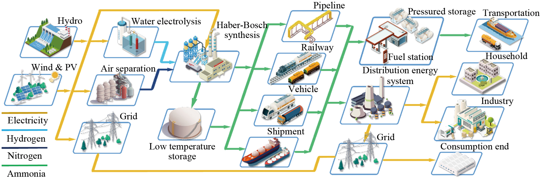
In this article, the carbon emissions and costs of ammonia production are analyzed from raw materials, production processes, and storage and transportation systems. Ammonia fuel combustion and emissions mechanism is analyzed, and an outlook on the application is given to provide a vision of a future ammonia-based zero-carbon energy system for transportation as shown in Fig. 1.
Ammonia, as one of the world's important chemical raw materials, is widely recognized for its zero-carbon and high energy density properties. Current mainstream technology routes and future development trends of ammonia synthesis, storage, transportation and application are summarized and outlooked in this paper.
In 1909, the Haber-Bosch process was invented for large-scale production of ammonia. Currently, as the largest contributor to global CO2 emissions, the Haber-Bosch process produces over 96% of the global ammonia, contributing 1.2% of global anthropogenic carbon dioxide emissions [21].
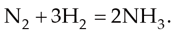
The synthesis of ammonia is an exothermic reaction that occurs spontaneously at low temperatures. However, the reaction rate is too slow at room temperature for industrial production. The reaction needs to be carried out under pressure 15–25 MPa, at high temperatures 400–450 °C, and with the help of catalysts to increase the transition rate. Hydrogen and nitrogen will react with the help of catalyst with the reaction equation with ΔG = –33 kJ/mol [21, 22]:(1)
Catalysts are critical for the ammonia reaction process. Molten iron catalysts currently dominate the industry for catalytic ammonia synthesis. The Haber-Bosch process for commercial synthesis is based on an iron-based catalyst with Al2O3 and potassium (K) as promoters and has been able to achieve efficiencies of up to 70% [23]. However, the process must need high temperature and pressure operation conditions. As for reducing energy consumption, ruthenium-based catalysts are developed to achieve the same efficiency as iron-based catalysts in a laboratory environment and are more active than the former. However, it has not been applied to large-scale production due to cost issues and its own toxicity at this stage [24]. The continuous improvement of new catalysts is a necessary research direction to further increase energy efficiency and lower costs. Atomic steps have dominated the catalyst surface reactivity for N2 activation, and catalysts such as ruthenium have been applied in advanced ammonia production processes due to their higher activity than iron [25]. Nørskov et al. [23] proved that the potential catalysts could act at lower temperatures by breaking the proportionality between the energies of two adsorption-surface interactions, leading to a significant reduction in cost and energy consumption.
Although there is a lower carbon ammonia production through technologies such as the electro-reduction of nitrogen to ammonia, the Haber-Bosch process will continue to dominate for the predictable future, as the energy consumption and production costs of the former methods are not at a level where it can be realistically produced [20].
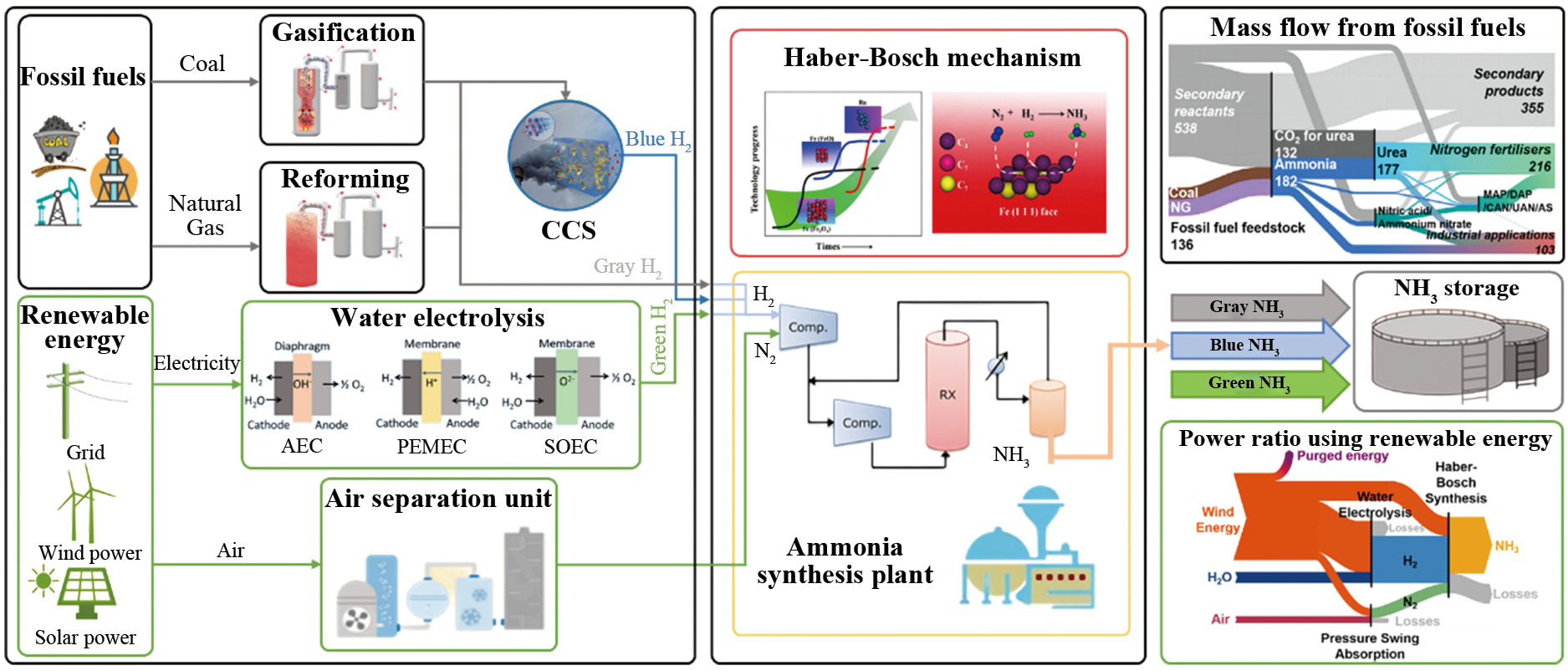
As illustrated in Fig. 2, ammonia can be categorized into three types based on the raw materials and processes: gray ammonia, blue ammonia, and green ammonia.
Gray ammonia is a high-carbon ammonia made from fossil fuels, and the main raw materials include natural gas (NG) and coal [20]. The mass flow of ammonia production from coal and NG is demonstrated in Fig. 2. Ammonia production from NG feedstock begins by mixing NG with a few hydrogen-containing gas, which is further preheated in a heater to approximately 450 °C [26]. The preheater then needs to be desulfurized to separate the sulfur impurities from it, as these impurities cause the catalyst to become less active. The second step is steaming reforming, and there are two main approaches, conventional steam methane reforming (SMR) and auto-thermal reforming (ATR). ATR is the combination of SMR and partial oxidation (POX). SMR converts methane and steam into syngas (CO and H2) by reacting the methane and steam, and the process requires heat absorption to proceed. ATR usually consists of methane reacting with steam and pure oxygen to form a syngas of CO, H2, and CO2 [20]. The SMR system is classified into a primary reformer and a secondary reformer. Water vapor and NG are supplied as the main reactants to the primary reformer, which serves to degrade the higher hydrocarbons to methane, thereby increasing the efficiency of downstream reforming. The most important variable in the SMR process is the steam/carbon ratio, which is a value usually in the range of 2–5 [27]. The gas after partial conversion is transported to a secondary converter, from where it is mixed with a volume of air [28]. Next, the synthesis gas will be transported to water-gas conversion unit, which is designed to react water vapor with the CO in the syngas to produce CO2 and more H2 [29]. The fourth step is the removal of carbon dioxide. The last stage is the methanation process to remove any residual CO and CO2 [25], as it can lead to catalyst failure in the Hubble process [20]. The final ammonia is formed in the ammonia synthesis loop.
Currently, China's top major source of ammonia is coal. The coal-to-ammonia production method is very close to the NG-based ammonia route, with the difference in the first step of treatment. Instead of SMR, the raw material is coal and oxygen from the air separation unit (ASU), which is converted to syngas by gasification in a gasifier [30, 31].
Blue ammonia is a low-carbon ammonia that uses CCS for carbon reduction based on the gray ammonia production process. For the blue ammonia facility currently in commercial operation, carbon capture focuses only on the SMR process. The structure consists of an acid gas removal unit (AGRU), carbon capture (CC) and carbon storage (CS) units. When synthesis gas is transported into the AGRU, it absorbs CO2 from it by contact with an aqueous solution. The CO2 is then released by heating the solution and the captured CO2 is compressed to 150 bars by the CC unit and cooled for transport and storage in the CS unit [27, 32]. Depending on the current technology for ammonia-based capture, CO2 capture rates of 85%–90% can be achieved. With further investment, it is possible to achieve capture rates of up to 99% in the future, which would result in near-zero carbon emissions from the SMR process. However, the application of CCS also increases energy demand, requiring approximately 0.7 GJ of additional electricity for each ton of ammonia produced [20].
Technologies related to carbon capture include adsorption, absorption, membranes, and cryogenic/low-temperature processes [30]. Adsorption is a physical process whereby molecules are immobilized on the surface of adsorbents. Adsorption processes currently include pressure swing adsorption (PSA), temperature swing adsorption (TSA), and electric swing adsorption (ESA). PSA is mostly related to the process of separating CO2 from higher-pressure syngas. For absorption, CO2 absorption is a relatively proven technology. The process is that CO2 is recovered by contacting and absorbing a liquid solvent in scrubber towers, and then the solvent is heated and/or depressurized. A commonly used approach is amine-based scrubbing, and a monoethanolamide (MEA) aqueous solution is employed to absorb the carbon dioxide synthesized therein and can be made to release it later by heating [27]. Membrane separation can be selective, where the portion passing through the membranes is permeable, while the portion not passing through the membranes is retained. The development of membranes for CO2 is a challenge due to its large molecular size. Matthew Anderson et al. proposed a carbonate-ceramic dual-phase membrane at high-temperature conditions for CO2 separation [33]. Cryogenic/low-temperature separation takes advantage of the different boiling points of gases, and to separate CO2, the gas mixture is cooling below the boiling point of carbon dioxide. An advantage of the process is that the CO2 is captured in liquid form, which is more easily transported by ship and other transportation means.
One of the main challenges facing CCS is the issue of storage. China currently has 1.19E11 tons of saline aquifers with CO2 reserves. It is planned to be able to utilize a CO2 storage capacity of up to 249 Mt/a in 2030, but this will only cover a small fraction of the CO2 captured by the application of CCS in production [34].
Green ammonia is produced by reacting green hydrogen based on water electrolysis. The renewable energy is utilized with nitrogen extracted from the ASU [35]. It could be a cleaner, greener energy source for the future [36]. Figure 2 shows the energy ratio for the synthesis of green ammonia using wind energy. There are currently three ways to electrolyze water, alkaline electrolysis, proton exchange membrane electrolysis, and solid oxide electrolysis. The basic principles of all three technologies are the same.
Alkaline electrolysis cell (AEC) is the most common electrolyzer for the production of green H2 [26]. AEC has been used commercially due to its technological maturity [37]. The solutions in AEC are mainly potassium hydroxide (KOH), sodium hydroxide (NaOH), and sulfuric acid (H2SO4), which form positive and negative ions thereby easily conducting electricity in aqueous solution. The materials of AEC are readily available, long-lasting, and exhibit relatively low costs [38].
Polymer electrolyte membrane electrolysis cell (PEMEC) is the second most proven electrolysis technology after AEC and can be applied to production. The main advantages of PEMEC are the use of solid polymer electrolytes, high compactness, flexibility of intermittent renewable power operation, and high voltage operation [35]. PEM electrolyzers use solid electrolytes such as sulphonated polystyrene. The anode and cathode chambers are isolated by a separator that serves to isolate hydrogen from oxygen with H+ transported in between. At the anode, water is depleted, while at the cathode, it is utilized to decrease the temperature. It has been achieved by circulating water between the two compartments [26].
As for solid oxide electrolysis cells (SOEC), the solid ion-conducting ceramics is utilized as electrolytes. It can operate at significantly higher temperatures (800–1000 °C) [38]. This type of electrolyzer has the lowest level of technological maturity and is not available in large-scale production. However, it is reported in lab-scale system development. The structure is composed of an oxygen-ion conduction membrane between the cathode and anode. To maintain reducing conditions at the cathode, a mixture of 90% vapor and 10% hydrogen is inlet to the cell. At the point of exit, H2 is utilized to further purify hydrogen using a condenser [26]. SOEC is expected to produce green H2 on a large scale because of its high efficiency at high operating temperatures.
Carbon dioxide emissions from ammonia production can be categorized into two kinds, hydrogen production from feedstock gasification and fuel combustion for heat supply [39]. Due to the distinctions in raw materials, the overall carbon emissions from the production process can vary widely. Figure 3(a) shows the range of Greenhouse Gas (GHG) emissions for different types. Overall, the production of 1 kg of gray ammonia can produce 1.92–4.6 kg of CO2 [40]. Zhou et al. proposed the emission factors for gray ammonia production in China. The emission factor from NG is 2.104 t(CO2)/t(NH3). However, the emission factor from coal could increase to 4.582 t(CO2)/t(NH3 ) [41, 42].
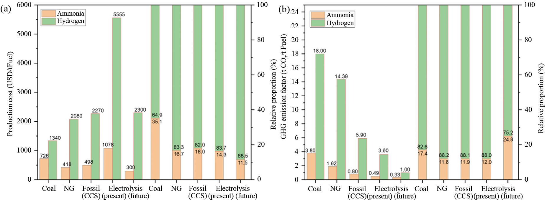
The production of blue ammonia could help to cause a decrease in the carbon emission figures due to the introduction of CCS. During the production process, the total CO2 emissions of blue hydrogen would be in the range of 0.67–1.16 kg(CO2)/kg(NH3) [32, 43, 44]. Different ways of steam reforming can also lead to different carbon emissions. Ref. [45] analyzed the impact of SMR and ATR on carbon emissions under CCS and showed that carbon emissions generated through the ATR approach would be more than 20% lower than the former. Green ammonia, which uses renewable energy, has the significantly lowest GHG emissions of the three production methods. Singh et al. predicted that 1.28 kg(CO2)/kg(NH3) would be produced through photovoltaic electrolysis, and the use of wind energy would reduce this number to 0.49 kg(CO2)/kg(NH3) [43]. Cameli et al. [46] built a model to analyze the 2019 scenario and predict the carbon emissions from e-NH3 and NG-based ammonia production in 2050. The 2050 scenario shows the lowest carbon emissions (0.33 kg(CO2)/kg(NH3)) when the wind was the source of electricity, which is consistent with previous literature, and only 0.36 kg(CO2)/kg(NH3) even under the 2019 projection. It is worth noting that if fossil energy-consuming grid electricity is used for ammonia synthesis from water electrolysis, the emissions would be as much as 12 times higher, and also 2.6 times higher than the ammonia production route using SMR. Liu et al. [47] differentiated between different nitrogen extraction techniques as well as electrolysis methods, where nitrogen obtained by low-temperature distillation and hydrogen generated using low-temperature electrolysis emits only 0.22 t CO2 per 1 t of ammonia synthesized.
The advantages of ammonia in the production process can be shown obviously. In comparison to hydrogen, the use of steam reforming for hydrogen would produce a maximum of 14.39 kg(CO2)/kg(H2), which would be reduced by 59% by the use of CCS. The lowest emissions come from wind energy production, which also produces 3.6 kg(CO2)/kg(H2) [48]. Overall, in terms of CO2 emissions, green ammonia currently has a significant advantage compared to gray and blue ammonia. In addition, ammonia shows large advantages in all production processes compared to the CO2 emissions of hydrogen.
The cost of ammonia production varies considerably from region to region due to differences in fuel and feedstock costs. Boulamanti et al. [49] analyzed the cost during the process of ammonia production in plants around the world. The production of 1 ton NH3 in a European plant would cost USD 364, while in Russia it was only USD 120, and in Saudi Arabia it was as low as USD 61. The operating cost of green ammonia mainly consisted of electricity, which was USD 390–430 per ton of ammonia produced by solar and on-road wind [50]. Lee et al. [44] analyzed the production costs of three kinds of ammonia. NG-based gray ammonia costed a minimum of 0.229 USD/kg(NH3), and the use of CCS adds 0.084–0.152 USD/kg(NH3) to this, while green ammonia is currently still higher at around 0.95 USD/ kg(NH3). A small number of large producer countries and regions are expected to have a fully decarbonized electricity grid in the short to medium term as sustainable development policies are implemented. Over the long term, the cost of green ammonia is expected to fall to a level on par with, or even lower than, the traditional fossil fuel route. The cost for production of ammonia is estimated to fall to USD 260–340 per ton by 2050 in most parts of China. The western and northern regions (e.g., Tibet, and Inner Mongolia) will be the most economical regions due to their abundant solar and wind resources [27]. In addition, Zhang et al. estimated that the production cost for green ammonia is now evenly matched with blue ammonia, down to 374 USD/t (NH3) [50]. Currently, the cost of green ammonia production for a new plant is currently assessed to be 720–1400 USD/t (NH3). It will drop to as low as 310 USD/t by 2050 when its cost will be more advantageous than grey and blue ammonia. Meanwhile, globally, the production cost for green ammonia in most parts of the world will be below 400 USD/t (NH3) [51].
Comparing the cost of hydrogen manufacturing, Philibert et al. [52] showed that the green hydrogen produced in Europe yielded a cost of 3–4 USD/kg(H2), which used a combination of solar wind energy. A large-scale hydrogen production from electrolytic water would need to run for about 1000 hours per year to get down to a cost of 2 USD/kg(H2). Ref. [53] listed the cost of hydrogen based on NG and coal at 1.1–1.5 USD/kg. Hydrogen production from electrolytic water is costly and wide-ranging, with a manufacturing cost of 3–6.7 USD/kg. In summary, grey and blue ammonia currently have advantages over green ammonia in respect of generation costs. However, the latter is also decreasing in line with the cost of sustainable energy and is showing better economics. Compared to the production costs of hydrogen, ammonia shows large strengths in a variety of production processes.
Although carbon emissions from ammonia production, mainly from gray ammonia, are currently at a high level, the aforementioned studies showed that the number would be reduced with the use of sustainable energy sources. Frattini et al. [54] suggested that theoretical zero carbon emissions can be achieved using a sustainable energy source to electrolyze water with ASU. The IEA also predicted that by 2050 ammonia's average CO2 emissions intensity would be 97% lower than the present data [20]. As the energy transition continues, green ammonia could decarbonize the existing ammonia market and displace fossil fuels for the foreseeable future. For costs, the IEA also forecasted the production cost of ammonia in China in 2050. The cost per ton of ammonia produced could be reduced to 260–340 USD in most regions, which would be lower than the production of grey and blue ammonia [20]. Besides, Governments and producers are implementing policies and programs to facilitate the transition to a near-zero-emission ammonia industry, which will provide better prospects for the development of our ammonia road map.
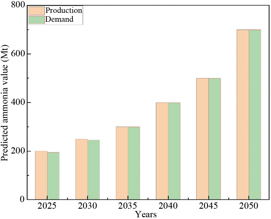
Ammonia, in terms of global chemical production, ranks second in production volume worldwide, only surpassed by sulfuric acid. At present, about 80% of ammonia is utilized in synthesizing nitrogen fertilizers, which ensures the food security of half of humanity. Renewable ammonia produced on an industrial scale from hydroelectric power has been available since 1920. However, the mainstream ammonia industry is now too dependent on fossil fuels and generates significant carbon emissions in the ammonia synthesis process. The production and demand of ammonia are mutually matched. The global output of ammonia was approximately 183 million tons in 2020. However, as global climate change intensifies and the energy transition proceeds, ammonia has been proposed for use as a fuel without carbon emissions or as a carrier for hydrogen storage, which is not implemented on a large scale currently. The demand and production capacity of ammonia will grow rapidly in the coming decades with new applications based on ammonia, with production capacity expected to reach 700 million ton by 2050 as shown in Fig. 4 [51].
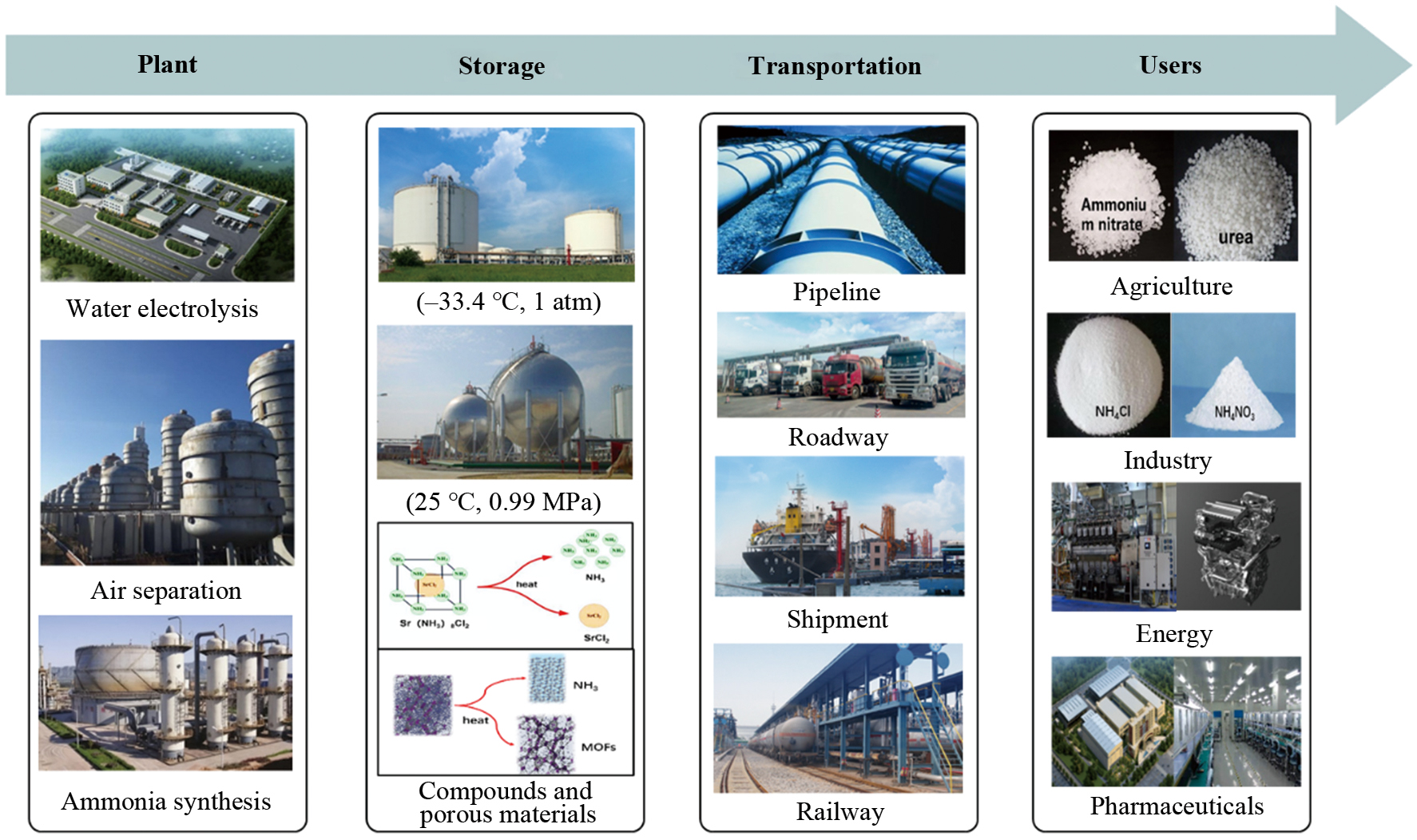
Based on the long-term production and application of ammonia, storage, transport and distribution methods of ammonia is highly sophisticated. In addition, training, industry standards, regulations, and laws ensure the guarantee of the industry. Not only in terms of technology, but also in the field of ammonia industry infrastructure the world has established a very complete ammonia infrastructure. In the United States, for example, there are 4830 km of ammonia pipelines which links ports, plants, and final customers [55]. International shipping routes already cover most of the world's countries and territories, and this trade network can make it convenient for ammonia to circulate globally as shown in Fig. 5 [56].
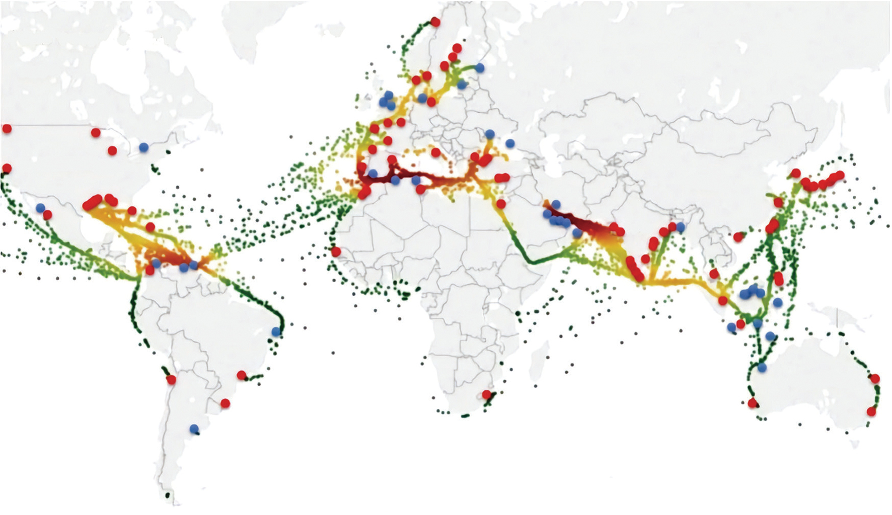
Although the great promise of ammonia in the energy field will allow ammonia capacity and demand to grow rapidly in the future, the existing ammonia industry system is sufficient to cope with the future expansion of the ammonia market without the need to duplicate the establishment of a new storage, transport, and distribution network. It is a huge advantage over hydrogen, which also has potential as an alternative fuel. Compared to ammonia, hydrogen has relatively little infrastructure and an inadequate transport network, and therefore development has been much more resisted than ammonia.
The costs and emissions during storage and transportation processes are similarly significant as production. As shown in Fig. 6, ammonia storage and transport technology are mature and the infrastructure is well developed globally. Ammonia has formed a complete storage and transport system with liquid storage as the main mode of storage and ship, railway, road, and pipeline transport as modes of circulation. Simultaneously, new solid-state storage and transport methods are being developed.
Due to its high critical temperature (132.5 °C), ammonia is easily liquefied and its state is liquid during storage and transport. There are three main storage methods. First, the liquefied ammonia can be stored directly under pressure in containers at ambient temperature, typically at a pressure range of 1.6 to 1.7 MPa. Second, low-temperature and atmospheric-pressure storage, that is, ammonia is liquefied at atmospheric pressure by lowering its temperature below –33 °C and stored in an insulated container. Third, medium-pressure low-temperature storage, that is, ammonia is liquefied and stored in adiabatic containers under a certain pressure at 0 °C. The first two are preferred, but it may be that a combination of pressure and temperature would be more economical.
Ambient temperature and high-pressure storage. Ammonia can be stored in liquid form at 0.8 to 0.9 MPa at an ambient temperature of 20 °C, where the energy density of ammonia is 13.77 MJ/L. 17 bar is the general working pressure of the ammonia pressure storage vessel. Ammonia remains liquid even when the ambient temperature rises [57]. If using ambient temperature and high-pressure storage methods, the sealing and strength of the tank will have greater requirements, generally using carbon steel spherical tanks or horizontal cylindrical horizontal tank structures. Ammonia has low volatilization losses and can maintain its liquid state without needing additional energy. The high pressure needed for ammonia storage poses a constraint due to the strength requirements of the vessel materials, which limits the size of the pressure vessel. The maximum size for ammonia pressure vessels is typically around 270 tons, and a general guideline is to store approximately 2.8 tons of ammonia for every ton of steel used in the construction [57]. This results in this type of storage being more suitable for road and rail transport or for small-scale, low-cost storage.
Low temperature and atmospheric pressure storage. To ensure economical and practical storage of ammonia or hydrogen on a large scale, the utilization of low-temperature storage techniques is frequently adopted. Ammonia can be stored as a liquid at ambient pressure as long as the temperature is maintained at –33 °C. This allows for efficient storage and transportation of ammonia, ensuring its availability for various applications. Two-stage refrigeration systems are used and stored ammonia is used directly as a refrigerant. The storage facility for ammonia utilizes a cooling system to maintain low temperatures. By cooling the ammonia upon entry, its energy density is increased to 15.37 MJ/L, which is slightly higher than the energy density of ammonia in pressurized storage, which is 13.77 MJ/L. This higher energy density allows for more efficient storage and utilization of ammonia as an energy source. Most tanks are also equipped with vapor recovery units to reduce ammonia losses and air pollution. The pressure in cryogenic liquefaction tanks is small compared to pressurized liquefaction tanks. As a result, tanks for low-temperature storage of ammonia can be designed with lower steel content, as they only need to meet the structural strength and insulation capacity to withstand hydrostatic pressure. However, this method requires an additional energy supply to maintain the temperature, and the tanks are more expensive to manufacture, so it is suitable for large-scale storage in ammonia plants or large harbors.
Although the liquid storage mentioned above has long been realized on a large scale, there are still some problems. Because of their capability to overcome cryogenic-high pressure conditions and their relatively low capital cost, carbon, and alloy steels have long been favored for ammonia storage applications. There is a special phenomenon of steel in liquid ammonia, called as stress corrosion cracking (SCC). This phenomenon can occur in both ambient-temperature and high-pressure tanks as well as in low-temperature and atmospheric pressure tanks. SCC can be considered a "brittle" failure mode because the material fails to exhibit its usual tensile strength and ductility [58]. To address this issue, residual stresses can be alleviated and low-yield strength metals can be utilized, however, these methods also work at a limited level.
Road, rail, and water transportation are all viable options for the transportation of both ammonia and hydrogen. They differ only in their storage conditions because each mode of transport takes a specific amount of fuel in storage containers. Both fuels can also be piped, which provides a continuous flow of fuel to the end users [57]. Difficulty in storage and transport is one of the bottlenecks constraining the development of hydrogen energy, while ammonia is easier to liquefy than hydrogen, and easier to store and transport [59, 60]. Liquid ammonia can be liquefied and transported at –33 °C under the same conditions and standard atmospheric pressure. However, if liquid hydrogen is transported directly, the temperature needs to be decreased to around –253 °C. In addition to this, ammonia is less expensive to transport and generates less carbon emissions during transport than hydrogen. Because of its higher energy density, ammonia is a more cost-effective and efficient option for transportation compared to hydrogen. When transporting ammonia, a single truck can carry up to 600 GJ of energy, whereas the same truck can only transport 48 GJ of energy when carrying compressed hydrogen [55].
The most commonly used transport mode of ammonia by road and rail is the use of pressurized tanks for transport, with a pressure generally around 1.6 MPa. There are also tankers for transporting highly concentrated ammonia with a maximum pressure of over 2 MPa. Railway carriers typically have a storage capacity of 60 t or more. Road transport has different sizes according to different transport terminals, and the capacity of large transport trucks is generally about 25 t [55, 57]. Because of the high cost of road transport, it is only suitable for short to medium distances or for terminal distribution transport. Hydrogen has a relatively low energy density compared to ammonia and is harder to liquefy, making it difficult to store and transport. The transport of compressed hydrogen in tanks takes 12 times less energy to transport compared to ammonia using an equivalent means of transport. If the liquefied hydrogen is being transported, then there is a clear rise in transport energy. However the process of hydrogen liquefaction is more difficult to achieve, and this process consumes a quarter of the energy of the liquid hydrogen transported. For rail transport, the effective capacity of a liquid hydrogen carrier is only about 7.5 t [61], which is nearly 10 times different from that of an ammonia rail carrier, so the cost of transporting hydrogen by road and rail is much greater than that of transporting ammonia.
The worldwide transport system for ammonia consists mainly of waterborne transport, which is much larger than road and rail transport. Waterborne carriers are generally large cargo ships with large storage capacity, so the atmospheric cryogenic method is used to achieve storage during transport. The general storage capacity of inland river carriers is 400–2500 t, and the maximum storage capacity of ocean-going carriers is 50,000 t, which is the largest in the world. Currently, there are about 170 vessels capable of transporting ammonia, of which about 40 are capable of transporting it continuously [55]. As for hydrogen, a hydrogen carrier from Kawasaki Heavy Industries in Japan made the world's first ocean transport of liquid hydrogen, but only in a volume of 75 t in 2022 [62]. Large-scale marine transport of hydrogen is not yet widely accessible, and the available data is primarily limited to theoretical calculations.
Using pipelines for transporting significant quantities of ammonia over long distances is a more cost-efficient choice in comparison to utilizing waterways or railways. In contrast to storage tanks, pipeline transport transports only ammonia, there is no need to move the means of transport, which reduces energy losses. A pipeline system comprises a pipe and a booster station, which serve the purpose of augmenting the pressure within the pipeline. This increased pressure is essential for overcoming friction losses and facilitating the movement of fluids through the pipelines [55]. The pipeline transport of hydrogen has had limited development. It is more susceptible to leakage and dispersion than ammonia because of the small size of the hydrogen molecule. Meanwhile, when the material is in contact with hydrogen over an extended duration, hydrogen invades the material, leading to the loss of metal materials, crack expansion speed up, and fracture toughness decline, that is, the "hydrogen embrittlement" phenomenon. It can be very fatal to the process of transporting hydrogen at high pressure, so there exist stringent regulations governing the selection of materials for manufacturing hydrogen pipelines. In addition, there are several technical hurdles to overcome, which have slowed the development of hydrogen pipelines compared to ammonia pipelines. Currently, there are about 2500 km of hydrogen pipelines in operation in the United States [63]. Most of China's hydrogen pipelines are hydrogen-doped transport pipelines, and there is currently no single pure hydrogen pipeline with a length of more than 100 km.
Solid-state ammonia storage is considered a means of safely storing ammonia and can significantly reduce the gas pressure of ammonia. Despite the added step of obtaining ammonia from the thermal decomposition of these materials, many of these compounds reach very high bulk ammonia densities when compacted into solid tablets [64]. Therefore, the storage advantages of ammonia are not significantly impaired. In Ref. [65], this type of storage is divided into two categories, one-way carrier and two-way carrier. A single-phase carrier converts ammonia into other compounds and then releases it again through a decomposition reaction. Biphasic carriers use the framework structure of the carrier to store ammonia molecules, and the carrier can be reused after releasing the ammonia molecules by heating. The conversion of ammonia into a non-toxic or low-toxicity compound is an essential requirement for single-phase carriers. Urea is produced by the reaction of ammonia and carbon dioxide, and ammonia or hydrogen can be released by hydrolysis or electrolysis, making it an ideal single-phase carrier. The other single-phase carriers similar to urea, such as ammonium hydroxide aqueous urea (AHU), ammonium hydroxide aqueous ammonium nitrate (AAN), and urea ammonium nitrate aqueous (UAN), have been proposed in Ref. [66]. Ammonium salts are another material in this category, such as ammonium sulphate, ammonium bicarbonate, etc. They can be used directly in fuel cells, eliminating the need for an ammonia production process, thus achieving zero end-user contact with ammonia and reducing the risk of poisoning and environmental contamination [67]. Bidirectional carriers are a diverse group of materials currently under development to facilitate the efficiency of storing ammonia. These carriers can absorb ammonia within their structural framework, resulting in increased bulk ammonia density and decreased vapor pressure. One is porous materials such as zeolites, activated carbon, carbon nanostructures, and organometallic frameworks. The second is amino metallic borohydrides with the general structure of M(BH4)m·nNH3, where M can be a single or double metal cation, which is thermally decomposed to achieve ammonia release [68]. The last type is ammonia storage metal ammonium salts, these complexes have the general form M(NH3)nXm, where M and X are metal cations and anions, respectively, and these complexes can be heated to recover ammonia [69].
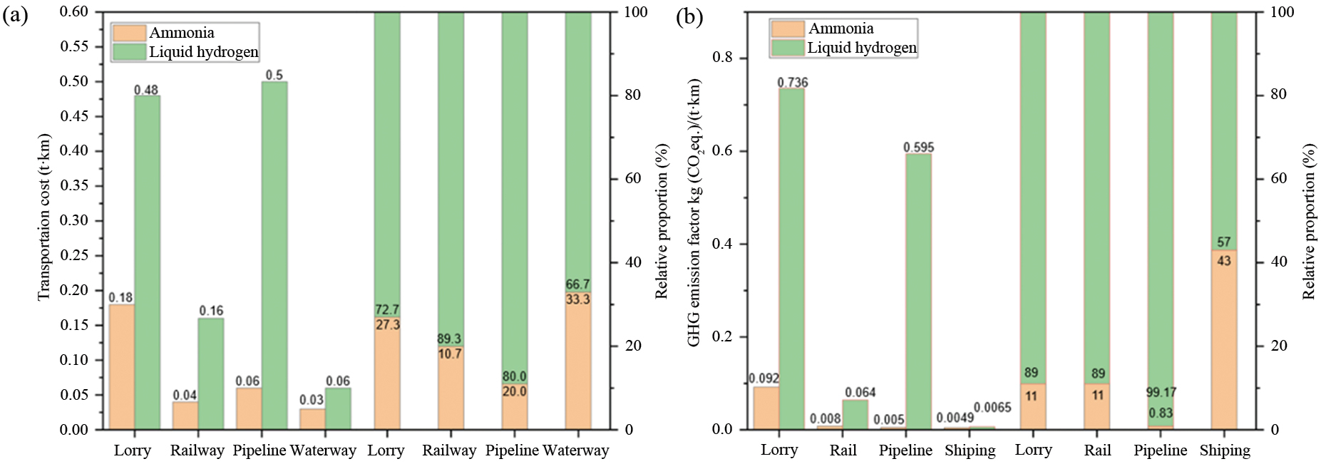
In terms of cost, the transport costs of ammonia and hydrogen were compared specifically for four forms of transport: road, rail, pipeline, and waterway, as shown in Fig. 7(a) [70]. Regardless of the mode of transport, transporting ammonia is significantly more cost-effective compared to transporting hydrogen. The fundamental reason for this is that ammonia and hydrogen have different physical properties. Transporting hydrogen poses challenges due to its difficulty in compression and liquefaction, requiring high pressures or low temperatures to maintain its state. These additional factors significantly contribute to the overall cost of the transportation process.
Figure 7(b) illustrates a comparison of carbon emissions from ammonia-hydrogen transport modes, and it can be seen that the carbon emissions from the transport of liquid ammonia are less than those of liquid hydrogen, regardless of the mode of transport [48, 71, 72]. Ammonia is stored at ambient temperature and high pressure during transport by road and rail, which consumes little energy other than the fuel of the means of delivery during transport. Therefore, it can be treated as a transport of ordinary liquid goods for the purpose of calculating carbon emissions. In contrast, hydrogen is much more difficult to store and transport, and its transport requires specific hydrogen transporters, such as liquid hydrogen tankers and long-tube trailers. They are more complex in structure and therefore have a limited effective volume, which leads to reduced transport efficiency and significant GHG emissions. In railway transport, only the payload weight is used as a comparative data due to the lack of other energy consumption of hydrogen during transport. Only carbon emissions from the ocean transport of ammonia and hydrogen are considered here because of the current slow development of hydrogen transport by water.
Currently, three commonly used hydrogen storage and transportation methods are high-pressure gaseous hydrogen transportation, liquid hydrogen transportation, and high-pressure transportation of deep-cooled hydrogen, but each method is difficult to operate, resulting in high transportation costs and inefficiencies. In contrast, ammonia presents the advantage of being more easily liquefied for storage and transportation. The whole industry chain covers upstream ammonia preparation, midstream ammonia storage and transportation, and downstream ammonia utilization, and should be deployed systematically. In addition to green ammonia synthesis, storage should be a comprehensive consideration of technical economy, safety, and other factors, to solve the large-scale liquid ammonia storage tank design and construction challenges. In terms of transportation, the overall planning of a long-distance liquid ammonia pipeline network applicable to energy development requirements should be investigated. At the same time, the ammonia storage and transportation system should be improved with ships, railroads, roads, and pipelines as the means of circulation to form a mature ammonia supply network. Facing the future ammonia fuel market and long-distance trade market, the green circular economy route of low-carbon and mild ammonia synthesis, safe and economic ammonia storage and transportation, and zero-carbon and high-efficiency ammonia utilization will be realized to finally form a whole industrial chain of ammonia energy application on a large scale.
Engines are complex thermodynamic machines. Considering the physical and chemical characteristics of ammonia, the use of ammonia in engines does not require major modifications to the engine structures [73, 74]. However, further efforts are needed in research on ammonia and mixed fuel combustion mechanisms, ignition methods, reprocessing, and fuel supply.
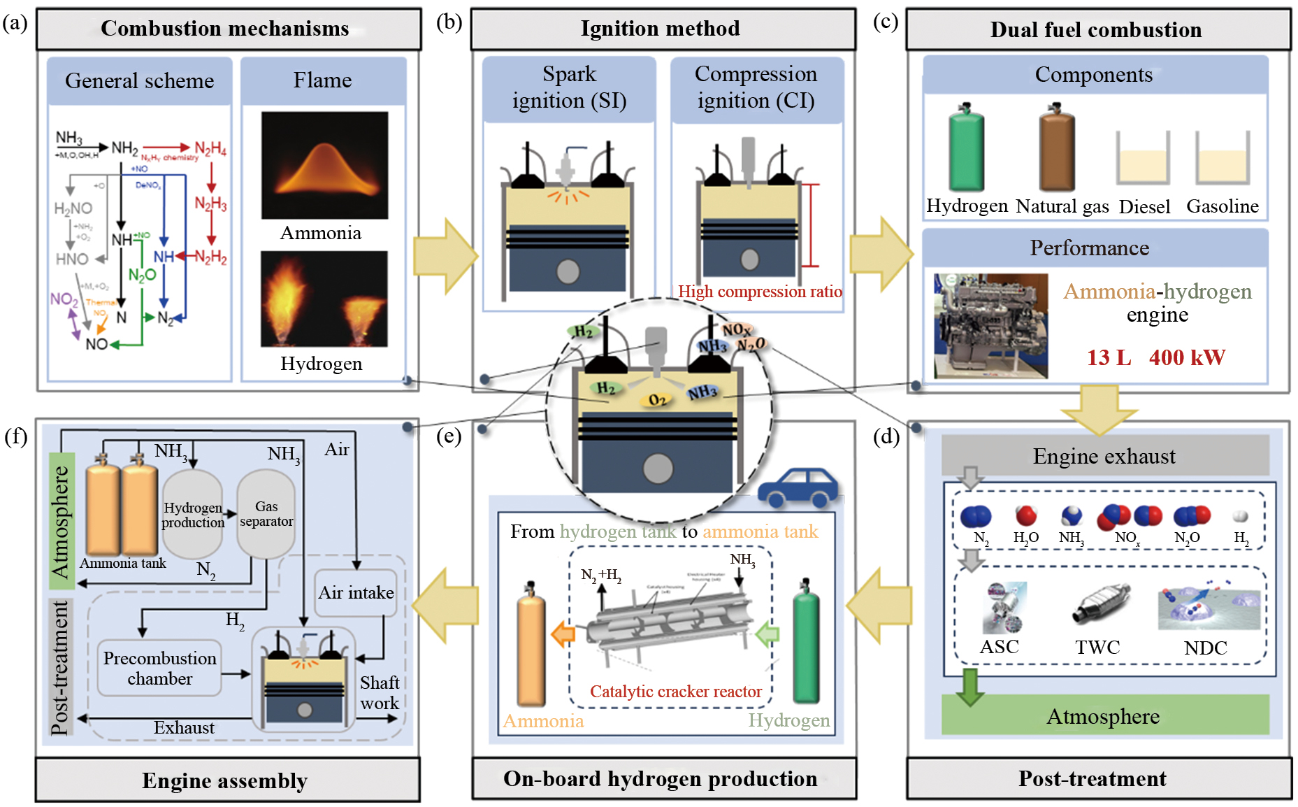
As shown in Fig. 8(a) the low cost and safety of transport for storage as a fuel is an advantage of ammonia over hydrogen. The absence of carbon emissions during direct combustion is an advantage of ammonia over conventional fossil fuels. However, ammonia's combustion inertia, high auto-ignition temperature, and low laminar flame speed limit the development of ammonia fuels [75, 76]. Studying of the kinetic mechanism of ammonia oxidation is the first task in the application of being a fuel and the basis for further research on combustion, flame morphology, emission mechanisms, and control. With long experimental and theoretical studies, the kinetic mechanism of ammonia oxidation has been achieved. The Miller model was an early mechanistic model proposed to describe the ammonia oxidation reaction process [77]. Konnov also used it as a basis for proposing a Konnov model capable of fuel-rich and high-pressure conditions [77], which was improved in the subsequent studies [78]. Although the application of these schemes has different temperature and pressure limitations, taken as a whole, they have been able to provide a general scheme for the kinetic mechanism of ammonia oxidation [79]. This can help researchers establish a reliable chemical mechanism of the ammonia combustion reaction in engine operating conditions, especially for ammonia-hydrogen engines.
Research on the combustion of ammonia in internal combustion engines (ICEs) consists of two periods. Firstly, in the 1960 s and 1970 s, researchers used ammonia for engines in response to the oil crisis. Secondly, the development of alternative fuels to mitigate carbon emissions from fossil fuel combustion has led to a resurgence of research on ammonia in the twenty-first century [73]. As shown in Fig. 8(b), ICEs can be categorized into two types: spark ignition (SI) and compression ignition (CI). Compression-ignition IC engines raise the temperature by compression to allow spontaneous combustion of the fuel in the cylinder. The high auto-ignition temperature of ammonia requires engines to use very high compression ratios. In the last century, researchers discovered that ammonia requires a 35:1 compression ratio for combustion in CI engines [80, 81]. Excessive compression ratios greatly increase the difficulty of applying pure ammonia to diesel engines and can adversely affect engine thermal efficiency, cylinder loads, and emission characteristics [82]. The use of fuels with low auto-ignition temperatures mixed with ammonia facilitates the reduction of the compression ratio required for auto-ignition [83]. As a result, the study on CI ammonia engines has shifted from pure ammonia fuels to ammonia blends. SI engines force the ignition of high temperature, high-pressure compressed fuel by emitting a high-energy electric spark at the end of the compression stroke or from a spark plug. Different from gasoline and diesel, ammonia has a significantly higher minimum ignition energy, thus necessitating the development of specialized high-energy ignition systems [74]. The latent heat of vaporization of ammonia is outstanding amongst common fuels and combustion is challenging to achieve combustion solely through direct injection of ammonia into the cylinder. The gasification of liquid ammonia in the cylinder absorbs a substantial quantity of thermal energy and produces cyclic changes, freezes the nozzles, and even leads to misfires [84]. Recently, China has developed a pure ammonia spark-ignition passenger car engine using high-energy ignition technology and pre-combustion chamber jet ignition technology, providing a demonstration of applied research on pure ammonia vehicle engines [85].
Dual-fuel ammonia engines using ammonia blends are an effective strategy compared to the disadvantages of pure ammonia fuels such as difficult ignition. Common ammonia fusion fuels include hydrogen, gasoline, diesel, and natural gas, as shown in Fig. 8(c). Ammonia-hydrogen fusion fuels, which are completely carbon-neutral, are receiving more attention. The investigation on ammonia-hydrogen engines has addressed ignition methods, combustion control, fuel supply, emissions, and aftertreatment. Both Ammonia and hydrogen possess a high octane rating. in terms of fuel characteristics, which makes them more suitable for SI engines than CI engines [86] ignition can be achieved by increasing the ignition energy. There have also been some attempts at novel ignition methods including pre-combustion chamber jet ignition, mean value CI, laser ignition, plasma assisted ignition, etc. [87]. Efficient combustion of fuel is one way to improve engine performance. Determining the ideal blend ratio of ammonia and hydrogen in ICEs is an actively researched subject. Some current research suggests that the best thermal efficiency for engines is expected to be achieved with a hydrogen fraction of around 20% [88, 89]. Aside from the proportion of hydrogen in the fuel mixture, the performance of an ammonia-hydrogen engine is influenced by several factors, including the equivalence ratio, compression ratio, and engine load. The study in this field requires high-precision numerical simulations. The limited knowledge regarding the oxidation mechanism of ammonia-hydrogen fuel during engine operation presents a significant difficulty in the development of ammonia-hydrogen engines.
Utilizing ammonia as an alternative fuel is a viable approach to reduce carbon emissions. As shown in Fig. 8(d), the exhaust gas components of the ammonia engine include N2, H2O, NH3, NOx, N2O, and very small amounts of H2. As with petrol and diesel engines, the emission of pollutants from exhaust gases should be limited using appropriate emission control systems. Unburned NH3 is a major source of emission pollution. In close proximity to the way hydrocarbon emissions from the petrol engines are produced, unburned ammonia originates from crankcase fouling and flame quenching at the cryogenic wall. Ammonia can be externally treated by employing an ammonia slip catalyst (ASC), which facilitates the oxidation of the ammonia present in the exhaust gas to N2. Another major pollutant in the exhaust is NOx, mainly NO, with small amounts of NO2 [90]. One part is the result of the oxidation of N2 by O2 in the air under high-temperature conditions within the combustion chamber, and the other part is the result of the continuous oxidation of ammonia in the combustion chamber. The more established NH3 aftertreatment strategies are recognized as three-way catalytic (TWC) and selective catalytic reduction (SCR) converters. Unlike petrol and diesel engines, N2O makes up a higher percentage of the exhaust. N2O is a potent greenhouse gas, with a global warming potential 300 times higher than that of CO2. Therefore, a specialized aftertreatment is required. N2O is usually a by-product of TWC and SCR. In the ammonia engines, N2O is interconverted with NO. At low temperatures, the reaction moves in the direction of increased N2O [91]. Promising for the efficient reprocessing of N2O are N2O decomposition catalysts (NDCs). NDC is in the research stage and it is worth further testing to see if it can operate efficiently in an engine aftertreatment system. H2 is derived from the decomposition of NH3 and unburned fuel. ASC is also capable of efficiently converting hydrogen if a suitable catalyst could be used [86]. In addition, in-cylinder control of ammonia engines is also a viable approach to mitigate emissions and alleviate pollution.
Experimental studies of ammonia-hydrogen engines at this stage usually use a stand-alone fuel fueling system. It is not reasonable to apply this model in vehicles. Separate ammonia and hydrogen cylinders cannot overcome the challenges of high hydrogen storage pressure in the gaseous state and low liquid storage temperature. Therefore, there is a need to develop an on-board ammonia-to-hydrogen plant that completes the ammonia-to-hydrogen conversion and separates the nitrogen from the cracked gas, as shown in Fig. 8(e). At the same time, this device can also solve the problem of fuel supply for ammonia-hydrogen fuel cells.
The reverse reaction of the Haber method, namely the decomposition of ammonia, can be facilitated by high temperatures and low pressures. These conditions are conducive to the endothermic reaction. The main technologies for efficient hydrogen production from ammonia include thermal catalysis and electrocatalysis. Ammonia thermal catalytic cracking requires the use of suitable catalysts. Ruthenium (Ru)-based catalysts are the most active mono-metal catalysts, while nickel (Ni)-based catalysts have better economic effect [92]. In on-board ammonia thermal crackers, the high temperatures required for catalysis (>400 °C) and the low purity of the hydrogen produced are disadvantages of thermal catalysis. In the case of ammonia engines, the low flame and exhaust temperatures are not easily met for efficient operation of the ammonia cracker, and the high temperature hydrogen produced needs to be cooled before it can be injected. Electrocatalytic decomposition of liquid ammonia is a method of generating high purity hydrogen that can meet the hydrogen purity requirements in hydrogen-fueled cells [93]. Research on the electrocatalytic decomposition of ammonia has progressed in the laboratory, but it has not yet been reliably applied in corporate production.
As shown in Fig. 8(f), taking into account the points raised, an ammonia-hydrogen hybrid fuel engine assembly strategy can be foreseen. A portion of the liquid ammonia stored in the tank is directed towards the onboard ammonia hydrogen plant to undergo the necessary processes for hydrogen preparation and purification. The other part is directly sent to the engine for in-cylinder direct injection. The ammonia-hydrogen engine adopts pre-combustion chamber jet ignition technology, where hydrogen is first burned in the pre-combustion chamber, and then injected into the cylinder. It is then mixed with liquid ammonia under the action of a high-energy electric spark. The exhaust gases are discharged to the atmosphere through an after-treatment section. Currently, there are limited studies on ammonia-fueled engine assemblies under such conditions, and most of them only consider specific aspects such as ammonia cracking, engine combustion, and injection strategies. The follow-up studies can consider ammonia-fueled engine assembly tests from the fuel tank to the exhaust pipe, which will have far-reaching significance for the development of ammonia fuel.
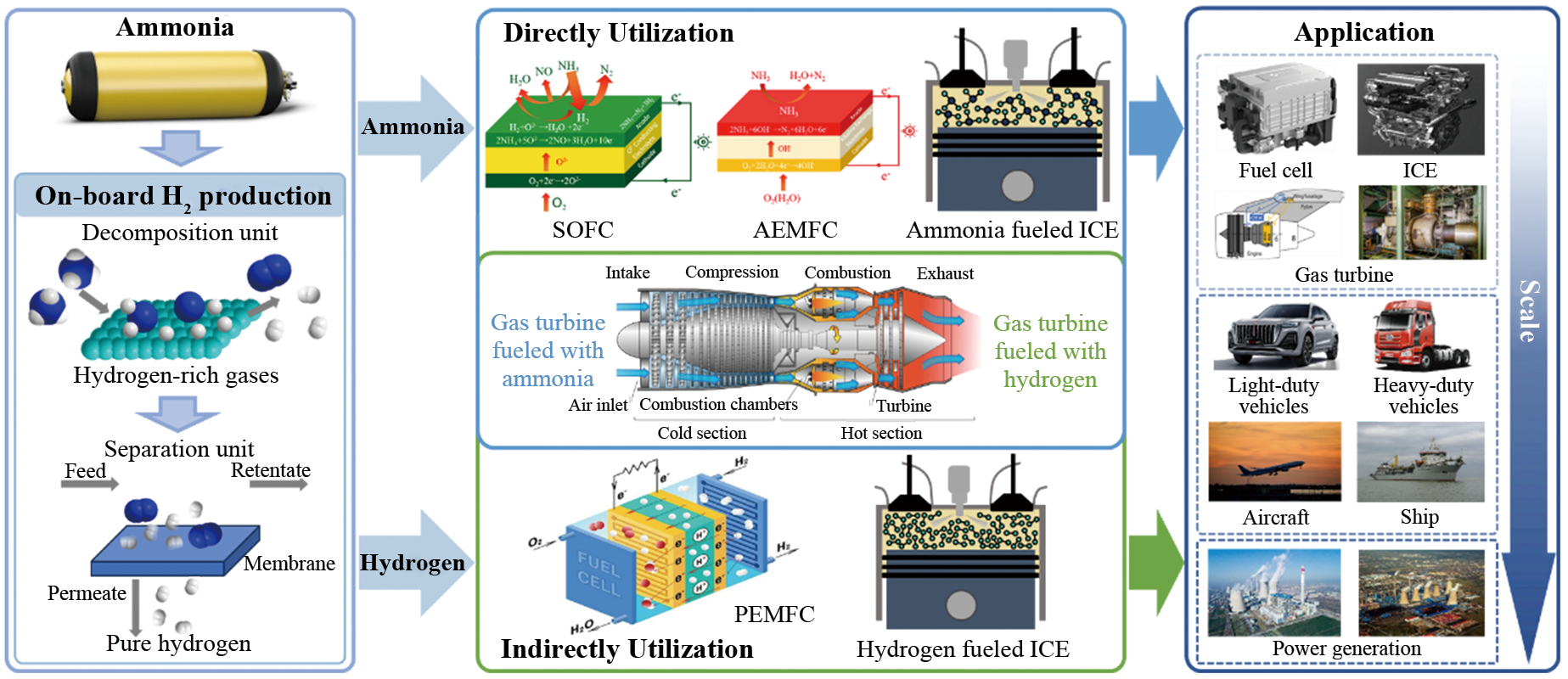
Ammonia, serving as both a clean fuel and an effective carrier of hydrogen, can be utilized for a variety of engines. Ammonia is also the lowest-cost fuel among fuels generated from renewable energy sources, and is anticipated to find applications across a broad spectrum of uses in the future as an economical and practical clean fuel in areas such as transport and stationary power generation, as shown in Fig. 9.
Indirect utilization of ammonia refers to the process of cracking and separation and purification of ammonia to obtain high-purity hydrogen, which is indirectly used in engines, for instance, hydrogen-fueled ICEs, hydrogen-fueled gas turbines (HFGTs), and indirect ammonia fuel cells (IAFCs). The HFGT is characterized by its high output power and wide range, and is more interchangeable with gas turbines for natural gas, allowing it to be mixed with natural gas. The IAFCs are generally the relatively technologically mature proton exchange membrane fuel cells (PEMFC), on basis of the transport of protons across a proton exchange membrane. Hydrogen, after losing electrons at the anode and converting to H+, crosses the PEM form water. Although power machinery is ultimately fueled by hydrogen, the indirect utilization of NH3 as a hydrogen carrier can reduce the cost of preparation and storage prior to the use of the fuels.
Direct use of ammonia refers to the application of ammonia as a fuel that is used directly in power machinery. Ammonia has the potential for direct utilization in various power machinery such as ammonia ICEs, direct ammonia FCs and GTs. Direct ammonia FCs can be divided into oxygen-ion conducting solid oxide fuel cells (SOFC-O), proton conducting solid oxide fuel cells (SOFC-H), alkaline membrane ammonia fuel cells (AEMFC), and so on, according to the electrolyte. A common feature of ammonia fueled SOFCs is the high operating temperature at which ammonia cracks to produce H2. The operating mechanism of SOFC-O is based on the transport of oxygen anions through the electrolyte. At the cathode, air is introduced and reduced to O2– at the cathode-electrolyte interface, which flow through the electrolyte. At the anode, ammonia is first cleaved to produce hydrogen, which then reacts with the O2– to form H2O. The anode produces a certain amount of NO because of the sluggish diffusion of oxygen anions through the electrolyte [94]. The operating mechanism of SOFC-H is based on the transport of protons through the electrolyte. At the anode, NH3 is decomposed to generate H2, which loses electrons in the presence of a catalyst and is converted to H+. H+ is transferred via the proton-conducting electrolyte to the interface between the cathode and solid electrolyte, where it reacts with oxygen to form H2O vapor [95]. The operation of AEMFC is based on the transport of OH– through the electrolyte. At the cathode, oxygen reacts with H2O to form hydroxyl ions, which pass through the electrolyte and react with ammonia to form nitrogen and water at the anode. AMFC operates at much lower temperatures and has higher efficiency of electrical energy conversion compared to SOFCs [96].
Research on ICEs, FCs, and GTs using ammonia-hydrogen fuels has demonstrated the feasibility of NH3 as a fuel. Academic and industrial exploration of ammonia applications on the ground in various countries in recent years has also given rise to many concepts and test prototypes of ammonia in vehicles, ships, aviation, rail transport, and stationary power generation.
Ammonia is mainly realized in vehicles through ammonia-fueled ICEs and FCs. In 2018, Ezzat and Dincer proposed two ammonia-fueled vehicle powertrain configurations, that is, an ammonia-hydrogen ICE alone or an ammonia-hydrogen ICE and a PEMFC to power the vehicle [97]. In both configurations, an Ammonia decomposition and separation unit is required to crack ammonia into H2 for the ICEs and PEMFCs. In 2021, a team from the Hong Kong Polytechnic University built an ammonia-powered fuel cell electric golf cart [98]. Ammonia stored in liquid form in steel cylinders decomposed into H2 under the presence of a catalyst. The unconverted ammonia was filtered through a gas purifier and the hydrogen obtained is used to generate electricity to propel the vehicle. In June 2023, Li's team at Tsinghua University and FAW Jiefang jointly developed China's first ammonia-hydrogen fusion direct-injection, zero-carbon, heavy-duty commercial vehicle internal combustion engine, which was successfully ignited and operated on 28 June 2023 [99]. In July 2023, Guangzhou Automobile Group (GAC) and Toyota jointly developed a liquid ammonia-powered engine, a 2.0-litre, four-cylinder engine that produces 161 hp and reduces carbon emissions by 90% [98].
The application of ammonia in ships relies mainly on ICEs and FCs. The high power rating of the ICE makes it the main power source for ships for some time to come. The power level of ammonia fuel cells has a large gap compared with that of internal combustion engines, which makes it difficult to meet the demands of ocean voyages and can be utilized as the main power of inland waterways and offshore vessels and the auxiliary power of ocean-going vessels at present [100]. In March 2022, China's first ammonia-powered 7000-car carrier independently developed and designed by Shanghai Shipbuilding Research and Design Institute (SSRDI), a subsidiary of China State Shipbuilding Corporation (CSSC), was awarded a Certificate of Approval-in-Principle (AiP) by Det Norske Veritas (DNV) [101]. In July 2022, NYK Line, Japan Engine Corporation, IHI Power Systems Co., Ltd., Nihon Shipyard Co. Ltd., and Nihon Shipyard Co., Ltd. received ClassNK's AiP certificate for the Ammonia Fueled Ammonia Gas Carrier (AFAGC). In July 2023, MAN Energy Solutions announced that it had successfully conducted the first ammonia engine test at its Copenhagen Research Center, which demonstrated the successful combustion of ammonia in a MAN B&W two-stroke 4T50ME-X engine [102]. In November 2023, Wartsila launched the world's first four-stroke ammonia ICE for the marine industry [103]. In November 2023, a medium-speed, high-power 12V240H-DFA ammonia-fueled ICE of China, independently developed by CSC Dalian, was successfully ignited. The ammonia-fueled engine has a power of up to 208 kW in a single cylinder, with an NH3 energy ratio of 85%. Ammonia-fueled engines emit 80% less carbon than conventional diesel-only engines. The ammonia-fueled engine is expected to be fitted to the country's first ammonia-fueled tugboat in the second half of 2024 [104]. Europe's Eidesvik offshore plans to apply an ammonia-powered fuel cell system to its supply vessel Viking Energy in 2024, making it the world's first long-distance, greenhouse gas-free supply vessel [105, 106].
Ammonia in aerospace applications mainly relies on GTs and FCs. Both the ammonia-fueled gas turbine and the hydrogen-fueled gas turbine can be used as engines to power aircraft. The non-coking properties of NH3 allow it to be utilized as a fuel as well as a coolant for compressor intercooling in gas turbines [107]. A study on ammonia as a zero-emission aircraft fuel was announced by Reaction Engines in 2020, hoping that by partially cracking NH3 into H2. The resulting ammonia fuel mixture will be used as an alternative fuel, enabling existing engines and aircraft to use zero-emission fuels [108]. Airbus is also looking to apply fuel cells to aircrafts [109]. In 2022, NASA's University Leadership Initiative selected a USD10 million, five-year project led by the University of Central Florida to explore the use of liquid ammonia as a carbon-free aviation fuel [110].
Ammonia is also expected to be used in rail transport applications. Currently, relevant research is focused on the use of SOFCs to co-generate electricity with other power generation units and to power railway systems. Al-Hamed and Dincer proposed a co-generation system for powering rail transport systems, which consists of an SOFC, and an AGT with an organic Rankine cycle of ammonia. They developed a thermodynamic model of the system. An optimal system energy efficiency of up to 71% is reach in the simulation, which is 12.9% higher than that of the SOFC-GT co-generation system [111]. In a subsequent study, the efficiency of this power generation system can reach 79.88% using passenger trains as the power supply [112].
The application of ammonia in stationary power generation is mainly dependent on gas turbines. Mitsubishi Heavy Industries (MHI) has successfully finished a combustion test of an ammonia mono-fuel burner for use in replacing some thermal power generation boilers. Next, MHI attempts to conduct combustion tests in a larger 4 ton/h combustion test furnace using an actual size burner. MHI will take steps to apply the burners that it has developed to thermal power plants in Japan and overseas [113]. Sembcorp in Singapore, IHI in Japan, and GE Vernova are looking to retrofit the existing gas turbines at the Sakra Power Plant in Singapore to use 100 percent ammonia fuel in the future [114].
For vehicles, the ammonia-hydrogen internal combustion engine could be the first ammonia-fueled power source suitable for widespread implementation, benefiting from advantages such as relatively low hydrogen demand and low hydrogen purity requirements. With the development of ammonia cracking and separation technology, indirect ammonia fuel cells are also expected to be widely used in vehicles when the cost and technical difficulties of cracking and separation are reduced. For heavy commercial vehicles with complex working conditions and variable loads, the ammonia-hydrogen fusion fuel composite powertrain comprises of the ammonia-hydrogen ICE and an indirect ammonia FC has theoretically optimal efficiency, and ammonia-fueled heavy-duty trucks are expected to become the mainstay of heavy-duty trucks.
For ships and airplanes, before further breakthroughs in the power level and power density of fuel cells, ammonia fuel cells can only be applied in scenarios with small loads and short mileage. The internal combustion engine will be the primary choice of power source for ships, and the application of marine ammonia internal combustion engine has already begun to show results, and ammonia-fueled ships in various countries are being developed vigorously. Ammonia will potentially help ship industries achieve zero carbon emissions sooner. Gas turbines as the primary choice of aircraft power source, ammonia gas turbines and hydrogen gas turbines are also a global research hotspot, ammonia will play an essential role in the zero carbon emissions of the aircraft.
For rail and stationary power generation, large ammonia GTs are already available and have demonstrated the potential of ammonia for use in conventional thermal power plants. Ammonia-fueled SOFC-GT hybrid systems have also been theoretically demonstrated to have higher energy efficiency, and ammonia can be a strong contender for green power generation.
Overall, as a superior carrier of hydrogen, ammonia is relatively mature in terms of preparation, storage, and transport, and its cost is lower compared to hydrogen. In the future, ammonia will find diverse applications in the realms of both transportation and stationary power generation. With the breakthroughs in ammonia cracking and separation research and the advancement of ICE, FC, and GT technologies, ammonia will become a non-negligible part of renewable energy.
Ammonia, as one of the most widely used chemical raw materials, has been mass-produced globally for over a century, while a relatively complete storage and transport system has been formed. In this review, the Haber-Bosch process synthesis method commonly is analyzed firstly, including green ammonia, gray ammonia, and blue ammonia. Despite its high energy consumption, the Haber-Bosch process would continue to dominate ammonia synthesis until the new low-carbon ammonia synthesis technologies reduce energy consumption and production costs. Then, the storage and transportation of ammonia are analyzed. The storage technology, transport network and distribution technology, infrastructure, industry norms, standards, and regulations are all relatively mature, and the existing ammonia industry system lays the foundation for future expansion of the ammonia market. Next, the combustion mechanism and combustion mode of ammonia are analyzed, and the strategy of potential dual-fuel ammonia ICEs is presented, providing a comprehensive demonstration of the scientific issues that hinder the application and popularization of ammonia-based ICEs. Finally, the application modes of ammonia in transport and stationary power generation are explored, and existing cases of ammonia applications are presented, with prospects for future commercial applications of ammonia. Based on the above analyses, this paper hereby presents some outlooks.
(1) Hydrogen production technologies should be developed with the consideration of utilizing renewable energy sources for water electrolysis. The efficient ammonia synthesis catalysts should be capable of operating at low temperatures and low pressures, thus leading to the large-scale application of cleaner and more economical ammonia synthesis.
(2) With the development of solid-state storage technology for ammonia, the bulk density of ammonia storage and transportation can be increased, the cost can be reduced, the transport efficiency and safety can be enhanced, and at the same time, the ammonia storage and transport system, which takes ships, railways, highways, and pipelines as the means of circulation, can be improved.
(3) The development of ammonia thermal cracking, electro-cracking, gas separation membrane hydrogen separation technology, proton exchange membrane hydrogen separation, and other technologies should be accelerated to help the application of ammonia to hydrogen in a low-energy, low-cost, high-efficiency manner.
(4) To increase the power density and reduce the cost of fuel cells, the combustion mechanism and emission control of ammonia fuel and ammonia-hydrogen hybrid fuel should be further investigated. The commercial application of ammonia-fueled ICEs, fuel cells and gas turbines should be promoted to lay out ammonia-fueled transport zero-carbon energy systems.
(5) The country needs to formulate relevant strategies to promote the green production and application of ammonia, and the government should introduce relevant incentive policies, formulate and improve the corresponding regulatory system, strongly support the development and application of ammonia fuel, and promote the demonstration projects related to ammonia fuels.
This work is supported by the National Natural Science Foundation of China under Grant No. T2241003.
United Nations, "The paris agreement," Online 2016, Accessed: May 1, 2024 [Online]. Available: https://www.un.org/en/climatechange/paris-agreement.
IEA, "CO2 emissions in 2022," Online 2022, Accessed: May 1, 2024 [Online]. Available: https://www.iea.org/reports/co2-emissions-in-2022.
O. Elishav, L. Mosevitzky, E. M. Miller, D. J. Arent, A. Valera-Medina, A. D. Grinberg, G. E. Shter, and G. S. Grader, "Progress and prospective of nitrogen-based alternative fuels," Chemical Reviews, vol. 120, no. 12, pp. 5352–5436, 2020.
C.W. Gross and S.C. Kong, "Performance characteristics of a compression-ignition engine using direct-injection ammonia–DME mixtures," Fuel, vol. 103, pp. 1069–1079, 2013.
C. Tornatore, L. Marchitto, P. Sabia, and M. De Joannon, "Ammonia as green fuel in internal combustion engines: State-of-the-art and future perspectives," Frontiers of Mechanical Engineering, vol. 8, p. 944201, 2022.
Valera-Medina, H. Xiao, M. Owen-Jones, W. I. David, and P. Bowen, "Ammonia for power," Progress in Energy and Science, vol. 69, pp. 63–102, 2018.
C. Zamfirescu and I. Dincer, "Ammonia as a green fuel and hydrogen source for vehicular applications," Fuel Processing Technology, vol. 90, no. 5, pp. 729–737, 2009.
A. Hayakawa, T. Goto, R. Mimoto, Y. Arakawa, T. Kudo, and H. Kobayashi, "Laminar burning velocity and Markstein length of ammonia/air premixed flames at various pressures," Fuel, vol. 159, pp. 98–106, 2015.
S. M. Grannell, D. N. Assanis, S. V. Bohac, and D. E. Gillespie, "The fuel mix limits and efficiency of a stoichiometric, ammonia, and gasoline dual fueled spark ignition engine," The Journal of Engineering for Turbines and Powers, vol. 130, no. 4, p. 042802, 2008.
A. J. Reiter and S. C. Kong, "Combustion and emissions characteristics of compression-ignition engine using dual ammonia-diesel fuel," Fuel, vol. 90, no. 1, pp. 87–97, 2011.
S. Oh, C. Park, S. Kim, Y. Kim, Y. Choi, and C. Kim, "Natural gas ammonia dual-fuel combustion in spark-ignited engine with various air fuel ratios and split ratios of ammonia under part load condition," Fuel, vol. 290, p. 120095, 2021.
C. W. Gross and S. C. Kong, "Performance characteristics of a compression-ignition engine using direct-injection ammonia DME mixtures," Fuel, vol. 103, p. 1069–1079, 2013.
J. Mao, X. Ma, Y. Ma, Z. Wang, Y. Zhang, and S. Shuai, "Optical diagnostic on HCII combustion characteristics for NH3-PODE3 dual fuel engine," Journal of Automotion Safety and Energy, vol. 13, no. 3, pp. 509–516, 2022.
C. S. Mørch, A. Bjerre, M. P. Gøttrup, S. C. Sorenson, and J. Schramm, "Ammonia/hydrogen mixtures in an SI-engine: Engine performance and analysis of a proposed fuel system," Fuel, vol. 90, no. 2, pp. 854–864, 2011.
IEA, "The role of low-carbon fuels in the clean energy transitions of the power sector,"Retrieved February, 2021, Accessed: June 1, 2024 [Online]. Available: http://www.iea.org/reports/the-role-of-low-carbon-fuels-in-the-clean-energy-transitions-of-the-power-sector.
Council for Science and Technology Policy, "Pioneering the Future: Japanese Science, Technology and Innovation [Brochure SIP]", Online 2021, Retrieved June 1, 2024, Accessed: May 1, 2024 [Online]. Available: https://www8.cao.go.jp/cstp/panhu/sip_english/sip_en.html.
S. H. Crolius, "Japan's electricity sector: An early market for low-carbon ammonia," Online 2020, Accessed: June 1, 2024 [Online]. Available: https://www.ammoniaenergy.org/articles/japans-electricity-sector-the-early-market-for-low-carbon-ammonia/.
S. Bruce, M. Temminghoff, J. Hayward, E. Schmidt, C. Munnings, D. Palfreyman, and P. Hartley, National hydrogen roadmap, Australia: CSIRO, 2018.
S. Bailey, "Yara at the forefront of clean ammonia in Australia," Online 2022, Accessed: June 1, 2024 [Online]. Available: https://www.yara.com.au/news-and-media/news/yara-at-the-forefront-of-clean-ammonia-in-australia/.
International Energy Agency, Ammonia Technology Roadmap: Towards More Sustainable Nitrogen Fertiliser Production, OECD Publishing, 2021.
C. Smith, A. K. Hill, and L. Torrente-Murciano, "Current and future role of Haber–Bosch ammonia in a carbon-free energy landscape," Energy & Environmental Science, vol. 13, no. 2, pp. 331–344, 2020.
M. Aziz, A. T. Wijayanta, and A.B.D. Nandiyanto, "Ammonia as effective hydrogen storage: A review on production, storage and utilization," Energies, vol. 13, no. 12, p. 3062, 2020.
J. Nørskov, J. G. Chen, K. Miranda, T. Fitzsimmons, and R. Stack, "Sustainable ammonia synthesis—Exploring the scientific challenges associated with discovering alternative, sustainable processes for ammonia, production,"U.S. Department of Energy, 2016, OSTIID1283146.
J. Qian, Q. An, A. Fortunelli, R. J. Nielsen, and W. A. Goddard III, "Reaction mechanism and kinetics for ammonia synthesis on the Fe (111) surface," Journal of The American Chemical Society, vol. 140, no. 20, pp. 6288–6297, 2018.
H. Liu, "Ammonia synthesis catalyst 100 years: Practice, enlightenment and challenge," Chinese Journal of Catalysis, vol. 35, no. 10, pp. 1619–1640, 2014.
G. Chehade and I. Dincer, "Progress in green ammonia production as potential carbon-free fuel," Fuel, vol. 299, p. 120845, 2021.
B. J. Shin, J. H. Mun, S. Devkota, S. M. Kim, T. H. Kang, S. A. Mazari, K. Cho, S. H. Kim, D. H. Chun, and K. M. Kim, "Comparative assessment and multi-objective optimization for the gray and blue ammonia synthesis processes: Energy, economic and environmental (3E) analysis," International Journal of Hydrogen Energy, vol. 48, no. 90, pp. 35123–35138, 2023.
B. Chen, Z. Liao, J. Wang, H. Yu, and Y. Yang, "Exergy analysis and CO2 emission evaluation for steam methane reforming," International Journal of Hydrogen Energy, vol. 37, no. 4, pp. 3191–3200, 2012.
A. I. Amhamed, S. Shuibul Qarnain, S. Hewlett, A. Sodiq, Y. Abdellatif, R. J. Isaifan, and O. F. Alrebei, "Ammonia production plants—A review," Fuels, vol. 3, no. 3, pp. 408–435, 2022.
M. Voldsund, K. Jordal, and R. Anantharaman, "Hydrogen production with CO2 capture," International Journal of Hydrogen Energy, vol. 41, no. 9, pp. 4969–4992, 2016.
V. Pattabathula and J. Richardson, "Introduction to ammonia production," Chemical Engineering Progress, vol. 112, no. 9, pp. 69–75, 2016.
R. W. Howarth and M. Z. Jacobson, "How green is blue hydrogen?" Energy Science & Engineering, vol. 9, no. 10, pp. 1676–1687, 2021.
M. Anderson and Y. Lin, "Carbonate–ceramic dual-phase membrane for carbon dioxide separation," Journal of Membrane Science, vol. 357, no. 1–2, pp. 122–129, 2010.
S. Chang, J. Zhuo, S. Meng, S. Qin, and Q. Yao, "Clean coal technologies in China: Current status and future perspectives," Engineering, vol. 2, no. 4, pp. 447–459, 2016.
B. Lee, L. R. Winter, H. Lee, D. Lim, H. Lim, and M. Elimelech, "Pathways to a green ammonia future," ACS Energy Letters, vol.7, no. 9, pp. 3032–3038, 2022.
K. Verleysen, D. Coppitters, A. Parente, W. De Paepe, and F. Contino, "How can power-to-ammonia be robust? Optimization of an ammonia synthesis plant powered by a wind turbine considering operational uncertainties," Fuel, vol. 266, p. 117049, 2020.
M. Rashid, M. K. Al Mesfer, H. Naseem, and M. Danish, "Hydrogen production by water electrolysis: A review of alkaline water electrolysis, PEM water electrolysis and high temperature water electrolysis," International Journal of Engineering and Advanced Technology, vol. 4, no. 3, 80–93. 2015.
O. Schmidt, A. Gambhir, I. Staffell, A. Hawkes, J. Nelson, and S. Few, "Future cost and performance of water electrolysis: An expert elicitation study," International Journal of Hydrogen Energy, vol. 42, no. 52, pp. 30470–30492, 2017.
W. Zhou, B. Zhu, Q. Li, T. Ma, S. Hu, and C. Griffy-Brown, "CO2 emissions and mitigation potential in China's ammonia industry," Energy policy, vol. 38, no. 7, pp. 3701–3709, 2010.
D. Ye and S. C. E. Tsang, "Prospects and challenges of green ammonia synthesis," Nature Synthesis, vol. 2, no. 7, pp. 612–623, 2023.
J. Brightling, "Ammonia and the fertiliser industry: The development of ammonia at Billingham," Johnson Matthey Technology Review, vol. 62, no. 1, pp. 32–47, 2018.
P. Arora, I. Sharma, A. Hoadley, S. Mahajani, and A. Ganesh, "Remote, small-scale,‘greener’routes of ammonia production," Journal of Cleaner Production, vol. 199, pp. 177–192, 2018.
V. Singh, I. Dincer, and M. A. Rosen, "Life cycle assessment of ammonia production methods," in Exergetic, energetic and environmental dimensions, Elsevier, 2018, pp. 935–959.
Kyuha Lee"Techno-economic performances and life cycle greenhouse gas emissions of various ammonia production pathways including conventional, carbon-capturing, nuclear-powered, and renewable production." Green Chemistry, vol. 24, no. 12, 4830–4844, 2022.
H. Council, "Hydrogen decarbonization pathways: A life-cycle assessment," Accessed: June 1, 2024 [Online]. Available: https://hydrogencouncil.com, 2021.
F. Cameli, A. Kourou, V. Rosa, E. Delikonstantis, V. Galvita, K. M. Van Geem, and G. D. Stefanidis, "Conceptual process design and technoeconomic analysis of an e-ammonia plant: Green H2 and cryogenic air separation coupled with Haber-Bosch process," International Journal of Hydrogen Energy, vol. 49, pp. 1416–1425, 2024.
X. Liu, A. Elgowainy, and M. Wang. "Life cycle energy use and greenhouse gas emissions of ammonia production from renewable resources and industrial by-products." Green Chemistry, vol. 22, no. 17, pp. 5751–5761, 2020.
M. Al-Breiki and Y. Bicer, "Comparative life cycle assessment of sustainable energy carriers including production, storage, overseas transport and utilization," Journal of Cleaner Production, vol. 279, p. 123481, 2021.
A. Boulamanti and J. A. Moya, "Production costs of the chemical industry in the EU and other countries: Ammonia, methanol and light olefins," Renewable & Sustainable Energy Reviews, vol. 68, pp. 1205–1212, 2017.
H. Zhang, L. Wang, F. Maréchal, and U. Desideri, "Techno-economic comparison of green ammonia production processes," Applied Energy, vol. 259, p. 114135, 2020.
C. Philibert, "Producing ammonia and fertilizers: New opportunities from renewables," IEA Report, pp. 1–6, 2017.
International Energy Agency, "An energy sector roadmap to carbon neutrality in China," Accessed: June 1, 2024, [Online]. Available: https://www.efchina.org/reports-en/report-lceg-2022030-2.
D. Frattini, G. Cinti, G. Bidini, U. Desideri, R. Cioffi, and E. Jannelli. "A system approach in energy evaluation of different renewable energies sources integration in ammonia production plants." Renewable Energy, vol. 99, pp. 472–482, 2016.
J. R. Bartels, A feasibility study of implementing an Ammonia Economy, Iowa State University Digital Repository, 2008.
R. Society, Ammonia: Zero-Carbon Fertiliser, Fuel and Energy Store: Policy Briefing, Royal Society, 2020.
B. Elishav, E. M. Mosevitzky Lis, D. J. Miller, A. Arent, A. Valera-Medina, A. G. Dana, G. E. Shter, and G. S. Grader, "Progress and prospective of nitrogen-based alternative fuels," Chemical Reviews, vol. 120, no. 12, pp. 5352–5436, 2020.
L. Jiang and X. Fu, "An ammonia-hydrogen energy roadmap for carbon neutrality: Opportunity and challenges in China," Engineering, vol. 7, no.12, pp. 1688–1691, 2021.
Y. Luo, Y. Shi, S. Liao, C. Chen, Y. Zhan, C.-T. Au, and L. Jiang, "Coupling ammonia catalytic decomposition and electrochemical oxidation for solid oxide fuel cells: A model based on elementary reaction kinetics," Journal of Power Sources, vol. 423, pp. 125–136, 2019.
R. Hudders, C. Dorf, and A. Holcombe, "Railway tank car for transcontinental shipment of liquefied hydrogen,"in Proceeding of Advances in Cryogenic Engineering, Springer, 1963, pp. 461–466.
Kawasaki Heavy Industries Ltd, "Liquefied Hydrogen Carrier -SUISO FRONTIER- Receives Classification from Nippon Kaiji Kyokai," Online 2021, Accessed: June 1, 2024 [Online]. Available: https://global.kawasaki.com/en/corp/newsroom/news/detail/?f=20211203_9557.
Department of Energy, "Hydrogen pipelines," Accessed: June 1, 2024 [Online]. Available: https://www.energy.gov/eere/fuelcells/hydrogen-pipelines.
R. Z. Sørensen, J. S. Hummelshøj, A. Klerke, J. B. Reves, T. Vegge, J. K. Nørskov, and C. H. Christensen, "Indirect, reversible high-density hydrogen storage in compact metal ammine salts," Journal of the American Chemical Society, vol. 130, no. 27, pp. 8660–8668, 2008.
R. Newman, "2.09-Stress corrosion cracking,"in Shreir's Corrosion, Oxford: Elsevier, 2010, pp. 864–901.
A. Grinberg Dana, O. Elishav, A. Bardow, G. E. Shter, and G. S. Grader, "Nitrogen‐based fuels: A power‐to‐fuel‐to‐power analysis," Angewandte Chemie-International Edition, vol. 55, no. 31, pp. 8798–8805, 2016.
K. R. Lee, D. Song, S. B. Park, and J. Han, "A direct ammonium carbonate fuel cell with an anion exchange membrane," RSC Advances, vol. 4, no. 11, pp. 5638–5641, 2014.
J. W. Makepeace, T. He, C. Weidenthaler, T. R. Jensen, F. Chang, T. Vegge, P. Ngene, Y. Kojima, P. E. de Jongh, and P. Chen, "Reversible ammonia-based and liquid organic hydrogen carriers for high-density hydrogen storage: Recent progress," International Journal of Hydrogen Energyy, vol. 44, no. 15, pp. 7746–7767, 2019.
C. H. Christensen, R. Z. Sørensen, T. Johannessen, U. J. Quaade, K. Honkala, T. D. Elmøe, R. Køhler, and J. K. Nørskov, "Metal ammine complexes for hydrogen storage," Journal of Materials Chemistry, vol. 15, no. 38, pp. 4106–4108, 2005.
The Rogal Society, Ammonia: Zero-carbon Fertiliser, Fuel and Energy Store, The Royal Society, 2020.
G. Di Lullo, T. Giwa, A. Okunlola, M. Davis, T. Mehedi, A. Oni, and A. Kumar, "Large-scale long-distance land-based hydrogen transportation systems: A comparative techno-economic and greenhouse gas emission assessment," International Journal of Hydrogen Energyy, vol. 47, no. 83, pp. 35293–35319, 2022.
X. Wu, B. Mao, Q. Zhou, J. Huang, and R. Tong, "Comparative of carbon emission factor levels in different modes of transportation industry," Journal of East China Jiaotong University, vol. 39, no. 4, pp. 41–47, 2022
C. Kurien and M. Mittal, "Review on the production and utilization of green ammonia as an alternate fuel in dual-fuel compression ignition engines," Energy Conversion and Management, vol. 251, p. 114990, 2022.
W. Cornelius, L. W. Huellmantel, and H. R. Mitchell, "Ammonia as an Engine Fuel,"1965 International Automotion Engineering Congress and Exposition, 1965, Accessed: June 1, 2024 [Online]. Available: Available:https://www.sae.org/publications/technical-papers/content/650052/.
L. Duan and T. Li, "Research progress of ammonia combustion characteristic and stable-combustion technology," Huazhong Keji Daxue Xuebao (Ziran Kexue Ban)/Journal of Huazhong University of Science and Technology (Natural Science Edition), vol. 50, no. 7, pp. 41–54, 2022.
M. Comotti and S. Frigo, "Hydrogen generation system for ammonia–hydrogen fuelled internal combustion engines," International Journal of Hydrogen Energyy, vol. 40, no. 33, pp. 10673–10686, 2015.
J. A. Miller, M. D. Smooke, R. M. Green, and R. J. Kee, "Kinetic modeling of the oxidation of ammonia in flames," Combustion Science and Technology, vol. 34, no. 1–6, pp. 149–176, 1983.
A. A. Konnov, "Implementation of the NCN pathway of prompt-NO formation in the detailed reaction mechanism," Combust Flame, vol. 156, no. 11, pp. 2093–2105, 2009.
C. Tornatore, L. Marchitto, P. Sabia, and M. De Joannon, "Ammonia as green fuel in internal combustion engines: State-of-the-art and future perspectives," Frontiers of Mechanical Engineering, vol. 8, p. 944201, 2022.
P. Dimitriou and R. Javaid, "A review of ammonia as a compression ignition engine fuel," International Journal of Hydrogen Energyy, vol. 45, no. 11, pp. 7098–7118, 2020.
J. T. Gray, E. Dimitroff, N. T. Meckel, and R. D. Quillian, "Ammonia fuel-engine compatibility and combustion,"Engineering, Chemistry, Corpus ID 135982531, 1966.
J. B. Heywood, "Automotive engines and fuels: A review of future options," Progress in Energy and Combustion Science, vol. 7, no. 3, pp. 155–184, 1981.
B. Wang, C. Yang, H. Wang, D. Hu, B. Duan, and Y. Wang, "Study on injection strategy of ammonia/hydrogen dual fuel engine under different compression ratios," Fuel, vol. 334, p. 126666, 2023.
M. Koike, H. Miyagawa, T. Suzuoki, and K. Ogasawara, "Ammonia as a hydrogen energy carrier and its application to internal combustion engines," Sustainable Vehicle Technologies, pp. 61–70, 2012.
X. Zhang, "World's first ammonia engine launched," Online 2023, Accessed: June 1, 2024 [Online]. Available: https://new.qq.com/rain/a/20230714A06GDB00.
Y. Qi, W. Liu, S. Liu, W. Wang, Y. Peng, and Z. Wang, "A review on ammonia-hydrogen fueled internal combustion engines," eTransportation, p. 100288, 2023.
Z. Liu, L. Zhou, and H. Wei, "Experimental investigation on the performance of pure ammonia engine based on reactivity controlled turbulent jet ignition," Fuel, vol. 335, p. 127116, 2023.
C. S. Mørch, A. Bjerre, M. P. Gøttrup, S. C. Sorenson, and J. Schramm, "Ammonia/hydrogen mixtures in an SI-engine: Engine performance and analysis of a proposed fuel system," Fuel, vol. 90, no. 2, pp. 854–864, 2011.
M. Dinesh, J. K. Pandey, and G. Kumar, "Study of performance, combustion, and NOx emission behavior of an SI engine fuelled with ammonia/hydrogen blends at various compression ratio," International Journal of Hydrogen Energyy, vol. 47, no. 60, pp. 25391–25403, 2022.
A. Mercier, C. Mounaïm-Rousselle, P. Brequigny, J. Bouriot, and C. Dumand, "Improvement of SI engine combustion with ammonia as fuel: Effect of ammonia dissociation prior to combustion," Fuel Communications, vol. 11, p. 100058, 2022.
S. Mashruk, E. Okafor, M. Kovaleva, A. Alnasif, D. Pugh, A. Hayakawa, and A. Valera-Medina, "Evolution of N2O production at lean combustion condition in NH3/H2/air premixed swirling flames," Combust Flame, vol. 244, p. 1122992022.
I. Lucentini, X. Garcia, X. Vendrell, and J. Llorca, "Review of the decomposition of ammonia to generate hydrogen," Industrial & Engineering Chemistry Research, vol. 60, no. 51, pp. 18560–18611, 2021.
Z. Wang, S. Zheng, Y. Yao, R. Chen, and Z. Wang, "Research progress on electrocatalytic decomposition of ammonia for hydrogen production," Huagong Xuebao/CIESC Journal, 2022.
O. Siddiqui and I. Dincer, "A review and comparative assessment of direct ammonia fuel cells," Thermal Science and Engineering Progress, vol. 5, pp. 568–578, 2018.
N. Q. Minh, "Ceramic fuel cells", Journal of the American Ceramic Society, vol. 76, no. 3, pp. 563–588, 1993.
R. Lan and S. Tao, "Direct ammonia alkaline anion-exchange membrane fuel cells," Electrochemical and Solid State Letters, vol. 13, no. 8, p. B83, 2010.
M. Ezzat and I. Dincer, "Comparative assessments of two integrated systems with/without fuel cells utilizing liquefied ammonia as a fuel for vehicular applications," International Journal of Hydrogen Energyy, vol. 43, no. 9, pp. 4597–4608, 2018.
J. Malayil, "Automaker GAC unveils world's first ammonia-powered engine for cars," Online 2023, Accessed: June 1, 2024 [Online]. Available: https://interestingengineering.com/transportation/gac-worlds-first-ammonia-engine.
Z. Li, Q. Shen, and Y. Dai, "Chinese scholars make breakthroughs in basic research on ammonia-hydrogen fusion zero-carbon power system for heavy-duty vehicles," Online 2023, Accessed: June 1, 2024 [Online]. Available: nsfc.gov.cn.
Y. Hu, M. Wang, L. Li, Z. Men, X. Zhao, Y. Zhu, and L. Liu, "Innovative Development of Ammonia-Hydrogen Powered Marine Ships in China," China Engineering Science, vol. 25, no. 2, pp. 133–146, 2023.
China State Shipbuilding Corporation Limited, "Ammonia fuel-powered 7,000-car car carrier", Online 2022. Accessed: June 1, 2024 [Online]. Available: http://www.csic.com.cn/n135/n171/n179/c22296/content.html.
Man Energy Solutions, "Ammonia for shipping," Online 2023, Accessed: June 1, 2024 [Online]. Available: https://www.man-es.com/marine/strategic-expertise/future-fuels/ammonia.
Wärtsilä Corporation, "Wärtsilä continues to set the pace for marine decarbonisation with launch of world-first 4-stroke engine-based ammonia solution," Online 2023, Accessed: June 1, 2024 [Online]. Available: https://www.wartsila.com/media/news/15-11-2023-wartsila-continues-to-set-the-pace-for-marine-decarbonisation-with-launch-of-world-first-4-stroke-engine-based-ammonia-solution-3357985.
China News Service Website, "China's first medium-speed, high-power ammonia-fueled engine ignites successfully," Online 2023, Accessed: June 1, 2024 [Online]. Available: https://www.chinanews.com.cn/cj/2023/11-30/10120580.shtml.
Eidesvik, "Viking Energy with ammonia-driven fuel cell," Online 2023, Accessed: June 1, 2024 [Online]. Available: https://eidesvik.no/viking-energy-with-ammonia-driven-fuel-cell/.
S. K. Janis Eitner, "The world's first high-temperature ammonia-powered fuel cell for shipping," Online 2021, Accessed: June 1, 2024 [Online]. Available: https://www.fraunhofer.de/content/dam/zv/en/press-media/2021/march-2021/imm-worlds-first-ammonia-powered-fuel-cell-for-shipping.pdf.
M. Otto, L. Vesely, J. Kapat, M. Stoia, N. D. Applegate, and G. Natsui, "Ammonia as an aircraft fuel: A critical assessment from airport to wake," The ASME Open Journal of Engineering, vol. 2, p. 031033, 2023.
Trevor Brown, "Zero emission aircraft: Ammonia for aviation," Online 2020, Accessed: June 1, 2024 [Online]. Available: https://www.ammoniaenergy.org/articles/zero-emission-aircraft-ammonia-for-aviation/.
Airbus, "Hydrogen fuel cells, explained," Online 2020, Accessed: June 1, 2024 [Online]. Available: https://www.airbus.com/en/newsroom/news/2020-10-hydrogen-fuel-cells-explained.
Jared Pike, "Purdue researchers part of NASA initiative to explore ammonia-based jet fuel," Online 2022, Accessed: June 1, 2024 [Online]. Available: https://engineering.purdue.edu/ME/News/2022/purdue-researchers-part-of-nasa-initiative-to-explore-ammoniabased-jet-fuel.
K. Al-Hamed and I. Dincer, "A new direct ammonia solid oxide fuel cell and gas turbine based integrated system for electric rail transportation," eTransportation, vol. 2, p. 100027, 2019.
K. Al-Hamed and I. Dincer, "A novel integrated solid-oxide fuel cell powering system for clean rail applications," Energy Conversion and Management, vol. 205, p. 112327, 2020.
Mitsubishi Power, "MHI succeeded combustion test of ammonia single-fuel burners -- Promoting the energy transition with CO2 emission reduction technologies for existing thermal power plants," Online 2023, Accessed: June 1, 2024 [Online]. Available: https://power.mhi.com/news/231128.html.
Julian Atchison. "Exploring ammonia retrofits at the Sakra power plant, Singapore," Online 2023, Accessed: June 1, 2024 [Online]. Available: https://www.ammoniaenergy.org/articles/exploring-ammonia-retrofits-at-the-sakra-power-plant-singapore/.
 Top