ContentsFigures & Tables
The high-speed railway (HSR) has become an impressive name card of China, providing a fast mode of transportation for people. It plays an important role in promoting economic and social development and the construction of the "Belt and Road Initiative".
Ensuring the safety and comfort of HSR is important for meeting the growing needs of people for a better life. For over half a century, the field of rail transit has continued a technological innovation characterized by high-speed, heavy-load, and electrification. It has run across regions with special geological conditions such as plateaus, deserts, permafrost, collapsible loess, and soft soil. High-speed trains regularly traverse long distances through harsh climatic areas such as extreme-cold, heavy rain, high-humidity, and strong wind conditions.
After China's HSR entered the long-term "maintenance" stage, the main scientific and technological challenges have become how to ensure the long-term smoothness and stability of different structural types of HSR lines to meet the public's expectations for HSR, such as transit safety, riding comfort, environmental friendliness and reliability.
Riding comfort is a universal need for travelers and it is also one of the main characteristics of the performance evaluation of high-speed trains. Being a comprehensive reflection and evaluation of passengers' travel quality, riding comfort is affected by many factors. This paper mainly considers factors that passengers passively accept, such as train performance and parameters of the railway lines. Factors that can be autonomously adjusted, such as temperature, lighting and seats, are not taken into account. Therefore, the index factors that affect passenger comfort are: train running stability, transient pressure inside the train, electromagnetic environment inside the train, noise inside the train, braking and longitudinal impulse, and centrifugal force in curves.
Train running stability is an evaluation of the vehicle's vibration as well as the vibration experienced by passengers [1]. It is usually based on the investigation of dynamic characteristics in the longitudinal, transverse, and vertical directions.
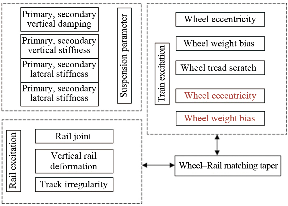
The vibration in an operating train is attributed to the combined effect of various factors [2–5], such as structural defects of the train components, track irregularity, wheel/rail contact behavior, aerodynamic force, and so on. When the train’s speed exceeds 200 km/h, the dynamic response changes dramatically. The resistance, vibration, and wheel-rail interaction affect the stability of the train during operation. The influencing factors and impact path are shown in Fig. 1.
Three main factors, vehicle dynamics, track dynamics, and matching behavior between wheel and rail, affect the stability of train operation. The suspension parameters of the train affect its vertical and lateral vibration.
Many countries and international railway organizations have established standardized stability evaluation systems. However, some standards treat stability evaluation the same as comfort evaluation. The rationality behind this needs to be investigated.
Chinese specification GB/T 5599 provides a comprehensive performance assessment methodology of rolling stock, which utilizes running quality, stability index, and comfort index as evaluation indexes. The running quality is characterized by the vibration acceleration of the train body. Other international standards that use vibration acceleration as an evaluation index are ISO 2631-1 [6], UIC518 [7], EN 14363 [8], EN 12299: 2009 [9, 10], and FRA [11].
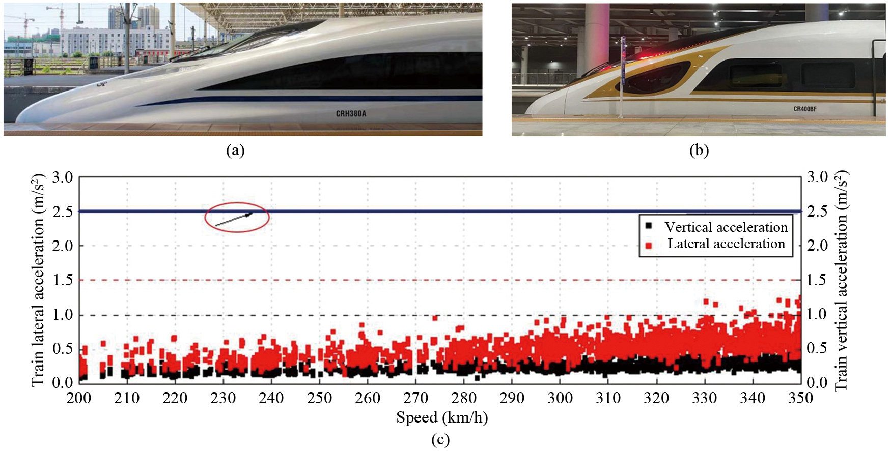
Different filtering intervals and weighting frequencies are specified in each standard. According to the methodology stated in GB/T 5599, the car body acceleration of the CRH380A electrical multiple units (EMU) measured on the Beijing–Shanghai HSR line is shown in Fig. 2. It can be seen that when the train speed is below 330 km/h, the vertical acceleration remains below 1 m/s2. When the train speed is 330–350 km/h, the vertical acceleration is below 1.5 m/s2. The lateral acceleration is always below 1 m/s2, indicating a high level of riding comfort.
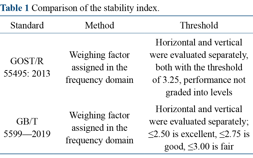
The stability index is divided into lateral and vertical directions with the same evaluation levels. The representative standards are Chinese standards GB/T 5599—2019 and GOST/R 55495: 2013, and a comparison is shown in Table 1.
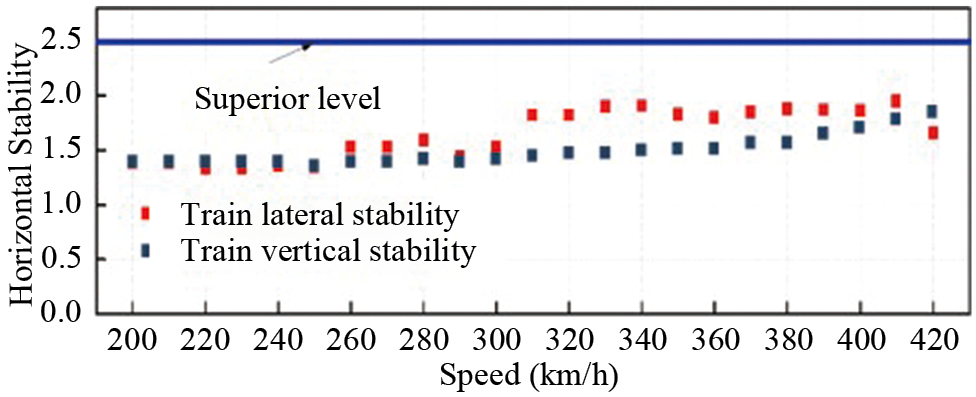
The test data of the "Fuxing" EMU on the Zhengzhou–Xuzhou HSR line is shown in Fig. 3. It can be seen from Fig. 3 that when the train speed does not exceed 300 km/h, the horizontal stability is around 1.5, and it becomes 2.0 at a speed above 300 km/h. The vertical stability is around 1.5 at 380 km/h and below. When the train speed is greater than 380 km/h, the vertical stability increases with the train speed. Nevertheless, the stability is always at an excellent level, indicating that the stability of "Fuxing" EMU satisfies the requirement.
Comfort index NMV is a comprehensive index that evaluates train performance and is widely used worldwide. The UIC 513-1994 standard [12] comprehensively evaluates and assigns weights to acceleration in three directions of the train body within the range of the maximum operating speed and obtains the ride performance evaluation index at a 95% confidence level. In the vertical and lateral directions, the maximum weighted frequency bands for acceleration are set at 4.0–16.5 Hz and 0.6–2.0 Hz, respectively. The evaluation index is 2.0 for the level "Comfort". British EN 12299:2009 and GB/T 5599—2019 adopt UIC 513-1994, and differentiate between average comfort index and continuous comfort index according to different measurement times. The threshold for average comfort index is 2.5.
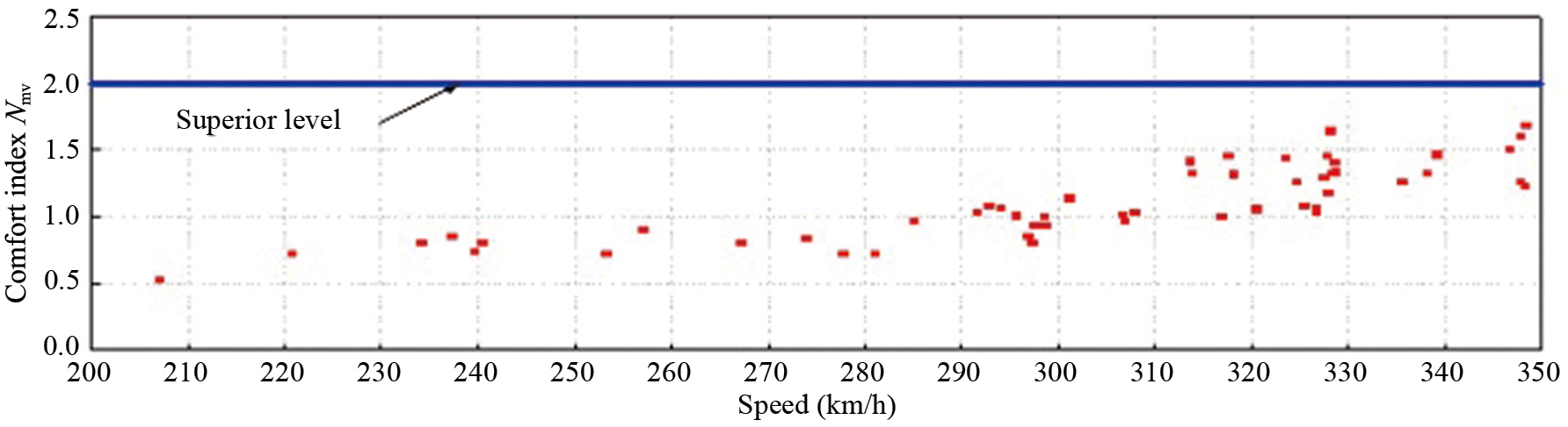
Statistical results of the comfort index NMV during the passage of the CRH380A EMU on the Beijing–Shanghai HSR are shown in Fig. 4. With the increase of the train speed, the value of NMV also increases. Nevertheless, the stability always satisfies the superior level requirement.
In recent years, with the increase of the HSR network as well as the number of high-speed trains in China, the performance of trains has deteriorated during operation and the vertical and horizontal vibrations have intensified, greatly affecting the stability and riding comfort and even threatening the safety of rail transits.
Under typical transient conditions such as head-on intersection of high-speed trains, tunnel intersection, and a single train passing through the tunnel, the vehicle surface will bear a transient pressure change of plus or minus kilopascals due to the pressure wave of train intersection or the compression and expansion wave generated when the train passes through the tunnel [13–16]. The complex pressure wave acting on the train surface will propagate to the interior of the incompletely sealed carriage within a short time, causing significan pressure fluctuations.
Higher transient pressure can severely affect the comfort of passengers and even cause dizziness and vomiting. The human ear is very sensitive to the transient pressure changes inside the vehicle. Generally speaking, a pressure fluctuation of 0.40–0.65 kPa/s will cause a sense of ear swelling. If the pressure fluctuation continues to increase, the symptoms will intensify, which may lead to the rupture of the eardrum and damage to the middle ear.
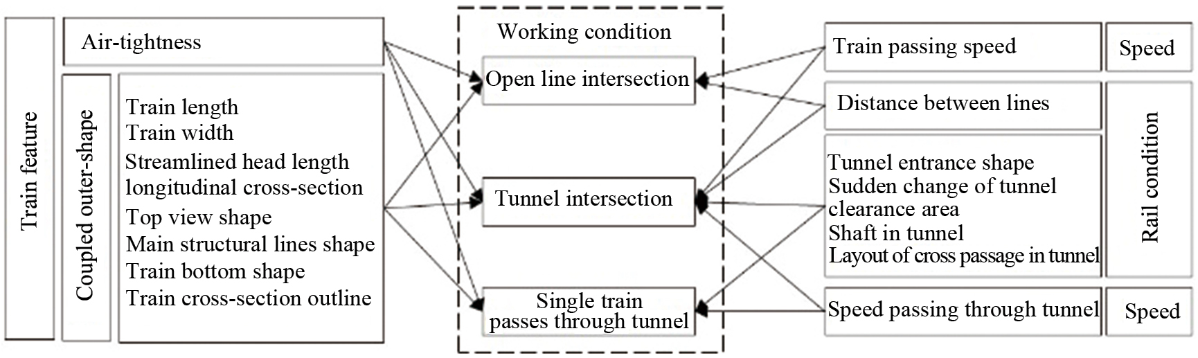
Over the years, existing studies on the aerodynamics of high-speed railways have proven that the main factors affecting transient pressure are train speed, track conditions, and train conditions. The impact pathway is shown in Fig. 5.
The air-tightness of the train directly affects the aerodynamic comfort inside the train [17]. Therefor, improving air-tightness can effectively alleviate the impact of pressure fluctuation on riding comfort.
During open line intersection, the transient pressure and running speed are in a power function relationship, where the amplitude increases with the increase of speed. Therefore, increasing the distance between railway lines can decrease the transient pressure.
When a single train passes through the tunnel, factors such as tunnel length, tunnel area, train cross-sectional area, the distance between adjacent tunnel openings, train length, etc., can all affect the pressure on the tunnel and the train’s surface.
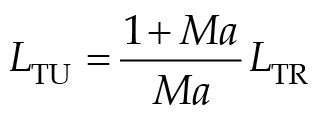
The most unfavorable tunnel length for a single train passing through the tunnel is calculated as:
During tunnel intersection, in the re-propagation process, various complex waves superimpose on each other and are reflected at the tunnel opening. Restricted by the tunnel wall, the air pressure wave does not diffuse as in the case of an open line intersection, causing greater pressure amplitude.
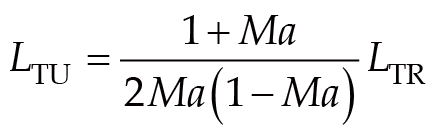
The most unfavorable tunnel length for double track rail tunnel intersection is calculated as:
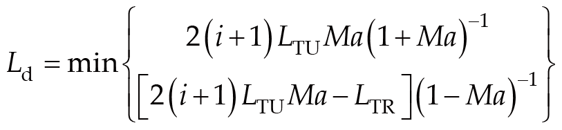
The relationship between the alternating pressure extreme value position in the tunnel and the length of the train and tunnel is expressed as:where LTU is the tunnel length; LTR is the total length of rolling stock; Ma is the Mach number; Ld is the distance between the alternating pressure extreme value position and the tunnel entrance; d is the distance to the tunnel entrance.
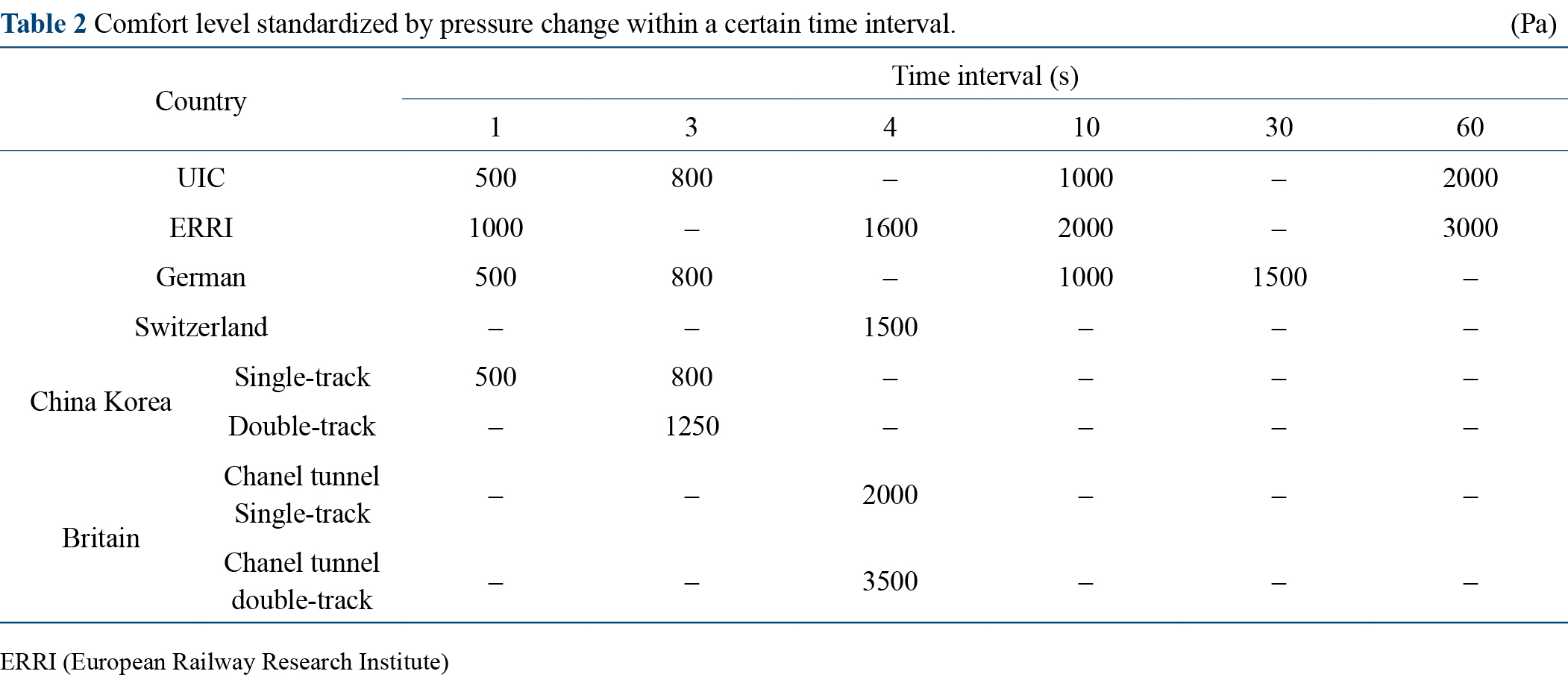
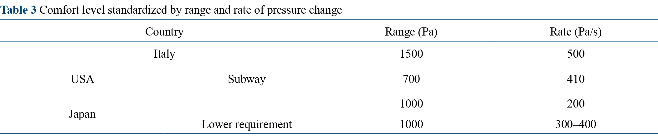
To evaluate the impact of pressure fluctuation on passengers' pressure comfort, HSRs abroad mainly adopt two types of comfort criteria. One is represented by the United Kingdom, Germany, UIC, and South Korea, expressed by the pressure change within a certain time interval, as shown in Table 2. Another is represented by Japan and Italy, expressed by the range and rate of pressure change, as shown in Table 3.
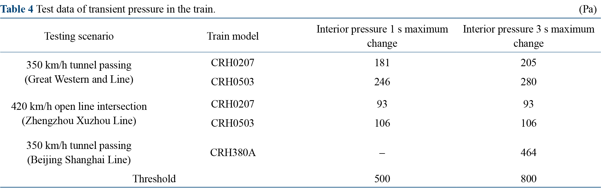
The air-tightness of China's independently innovated high-speed train has reached a cutting-edge level, with an excellent aerodynamic comfort level that is consistent with the most stringent UIC standard in the world. Test data of scenarios are shown in Table 4.
It can be seen from Table 4 that the transient pressure in China's HSR EMUs is far lower than the limit value, with multiple groups less than half of the limit value, showing excellent performance.
In order to establish a train aerodynamic environment that meets the requirements of high comfort and prevents injuries to passengers under alternating pressure, the transient pressure should be further controlled from perspectives such as refined flow testing technology and equipment for high-speed railway transit flow field, improving air tightness of trains and optimizing the geometric dimensions of the tunnel entrance.
The electromagnetic environment inside the train is the sum of the electromagnetic phenomena of high-speed trains [18–20]. With the development of HSR technology and increasing awareness, the impact of the electromagnetic environment on the health of passengers and crew has attracted more and more attention.
The HSR electrification system integrates traction power supply equipment, pantograph catenary contact equipment, and information transmission equipment. The electromagnetic waves of each piece of equipment generated during operation constitute the electromagnetic environment of the whole HSR system.
Traction power supply system: of 25 kV from the contact network is converted into several megawatts of traction power through the traction system, and a certain amount of electromagnetic radiation is generated in high-power conversion. When the traction system of high-speed EMU usually operates, because the traction system adopts AC-DC-AC energy transmission mode, a large number of high-order harmonics are generated in this process. These high-order harmonics directly radiate electromagnetic energy into the air. The higher the running speed, the greater the traction power required and the stronger the electromagnetic interference generated. During the train's acceleration, traction power changes greatly, resulting in drastic changes in the magnetic field; high-capacity traction motors, traction converters, transformers, and other electronic devices, such as low-capacity sensors, all produce electromagnetic interference in the working process.
Pantograph catenary system: when the sliding plate of the pantograph contacts the contact line of the catenary, a large amount of electromagnetic interference is generated in the process of pantograph catenary separation, pantograph raising, and excessive equality. During the operation of EMU, the pantograph obtains 25 kV single-phase AC from the catenary. To balance the load of the power supply system, the train must "change phase" after traveling for a certain distance and go through the process of "over-current phase separation". The change of contact between the pantograph and the catenary during phase separation produces a high-frequency and strong pulse arc between the pantograph and the catenary, which radiate electromagnetic energy around the train.
In the information transmission system, many power cables and communication cables are densely arranged in the limited space under the train, which further complicates the electromagnetic environment in the train.
The International Commission on Non-Ionizing Radiation Protection (ICNIRP) established standards titled "Guidelines for Limiting Exposure to Electromagnetic Fields" [21] in 1998. It made detailed provisions on the exposure of occupational and public electromagnetic fields, which has become the reference standard for controlling electromagnetic radiation environments worldwide. In 2010, the guideline revised the provisions for low-frequency electromagnetic fields less than 100 kHz. Moreover, the induced electric field intensity and magnetic induction intensity B were used to replace current intensity as the physical quantity for limiting exposure to electromagnetic fields.
In 2014, China established standards titled "Limits for Controlling the Electromagnetic Environment (GB 8702–2014)", and added control limits for electromagnetic exposure to 1–100 kHz electromagnetic fields. Both ICNIRP and GB 8702–2014 standards used electric intensity and magnetic induction intensity as physical quantities to limit the power frequency of electric fields.
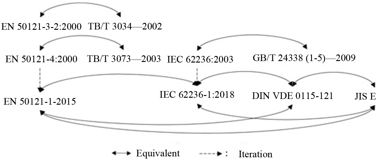
International railway standards [22, 23] such as the IEC 62236-1-2018, the European standard EN 50121-1: 2015, the German Association for Electrical, Electronic & Information Technologies standard DIN VDE 0115-121, and the Japanese Industrial Standards Committee JIS E5006 standard are essentially equivalent or adopted with equivalence. That is, the same standard is transformed between different organizations. The iteration and equivalence relationship of the same standard are shown in Fig. 6.
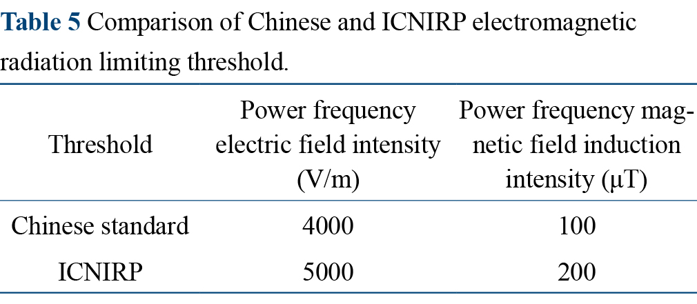
Considering the potential effects of electromagnetic radiation on passengers and staff, China has stipulated stricter standards for 0–20 kHz low-frequency magnetic field in EMU compared to other international standards, specified in the "Limits and methods of measurement of the low-frequency magnetic field inside Multiple Units", as shown in Table 5
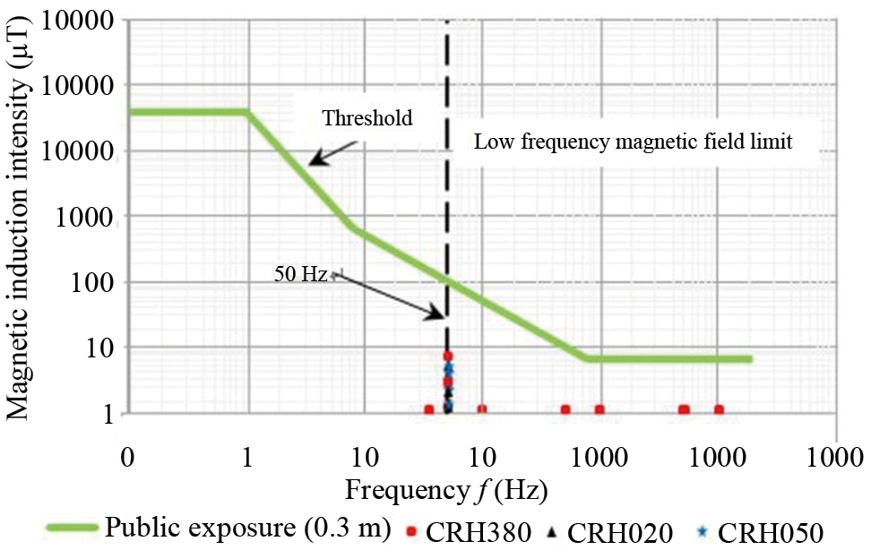
Through years of research, the study of electromagnetic compatibility characters and electromagnetic environment unique to China's HSR system is relatively mature. The test results of each measuring point in the carriage of high-speed EMU are shown in Fig. 7. It can be seen that the magnetic induction intensity inside the carriages of CRH380A, CRH0207, CRH0503 and other trains are far lower than the limit value of public exposure.
There are three kinds of suppression technologies for electromagnetic interference: filtering, shielding, and grounding. Among the three suppression technologies, shielding and grounding are more commonly used. Due to the limitations of filtering technology and the conditions of high-speed EMUs face significant constraints. Therefore, the electromagnetic compatibility of the new generation of EMUs should not only meet the needs of China's HSR development, but also operate normally in the complex electromagnetic environment without causing electromagnetic interference to any other equipment (including human bodies) in that environment.
The interior noise [24, 25] inside the high-speed train, which interferes with the daily activities of the passengers on the train or interferes with the sound that the passengers do want to hear, directly affects the comfort of passengers. The continuous high-intensity noise may cause fatigue, anxiety, or a sense of pressure and tension, which hurts people's physical and mental health. At the same time, the issue of interior noise also restricts the further increase in the operating speed of commercial high-speed railways.
The interior noise of high-speed trains is mainly composed of wheel-rail noise, traction system noise, collector system noise, and aerodynamic noise.
Wheel-rail noise is affected mechanism, wheel-rail noise can be divided into rolling noise, impact noise and curve squeal. Rolling noise is primarily affected by the geometric state of the wheel and rail surface and the roughness of the wheel-rail contact surface; the geometric state of the wheel-rail interface, rail joint, and the wheel-rail surface damage affects the impact noise; curve radius affects curve squeal. The noise of the traction system is closely related to training speed and load, including the electromagnetic noise of the motor in the auxiliary equipment, the meshing noise of the gears, and the sound radiation coming from components resonance that is excited by gear transmission. The noise of the collecting system mainly comes from the pantograph catenary area at the top of the train. Under high operation speed, the arc noise is generated due to the influence of the pantograph off-line; under low operating speed, sliding noise is generated due to the sliding between the sliding plate and the contact line. It is generally believed that arc noise is directly proportional to the sixth power of velocity, while sliding noise is directly proportional to the square of velocity. Aerodynamic noise mainly comes from the interaction between air and the mounted devices or special structures on the train surface. The shape of the train head is also a major factor affecting aerodynamic noise.
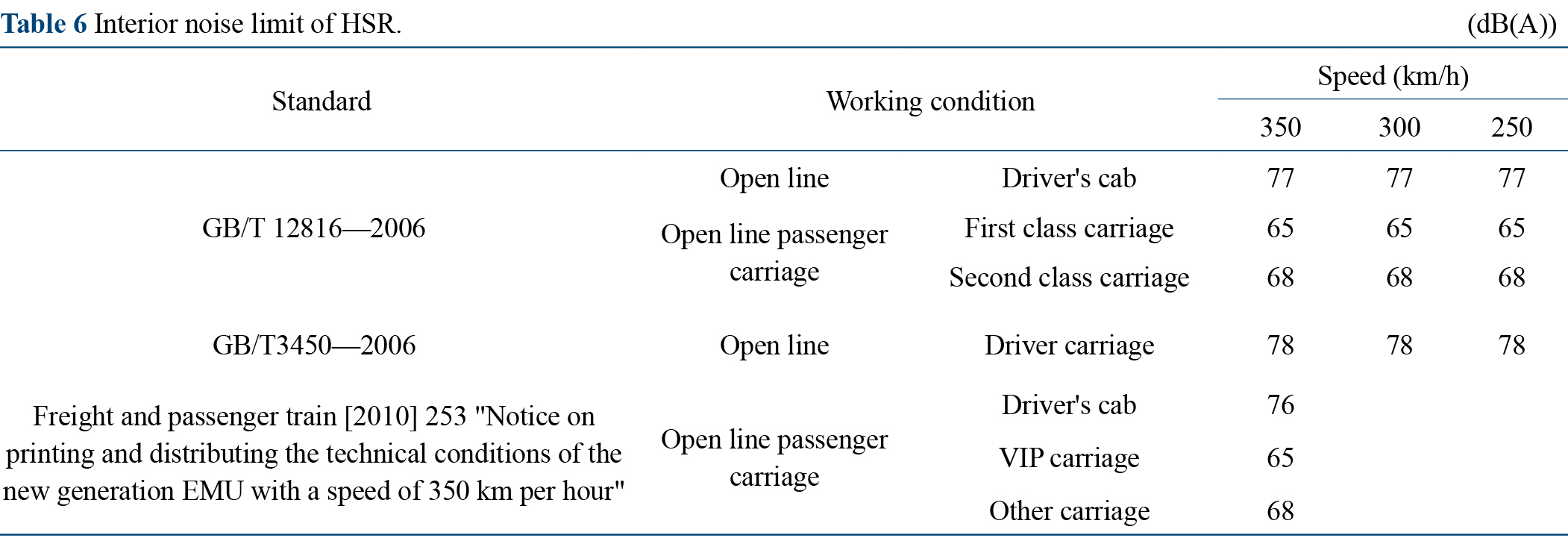
To effectively control the interior noise of high-speed trains, noise limits at different speed levels have been formulated worldwide. The interior noise limits of representative standards [26] are shown in Table 6.
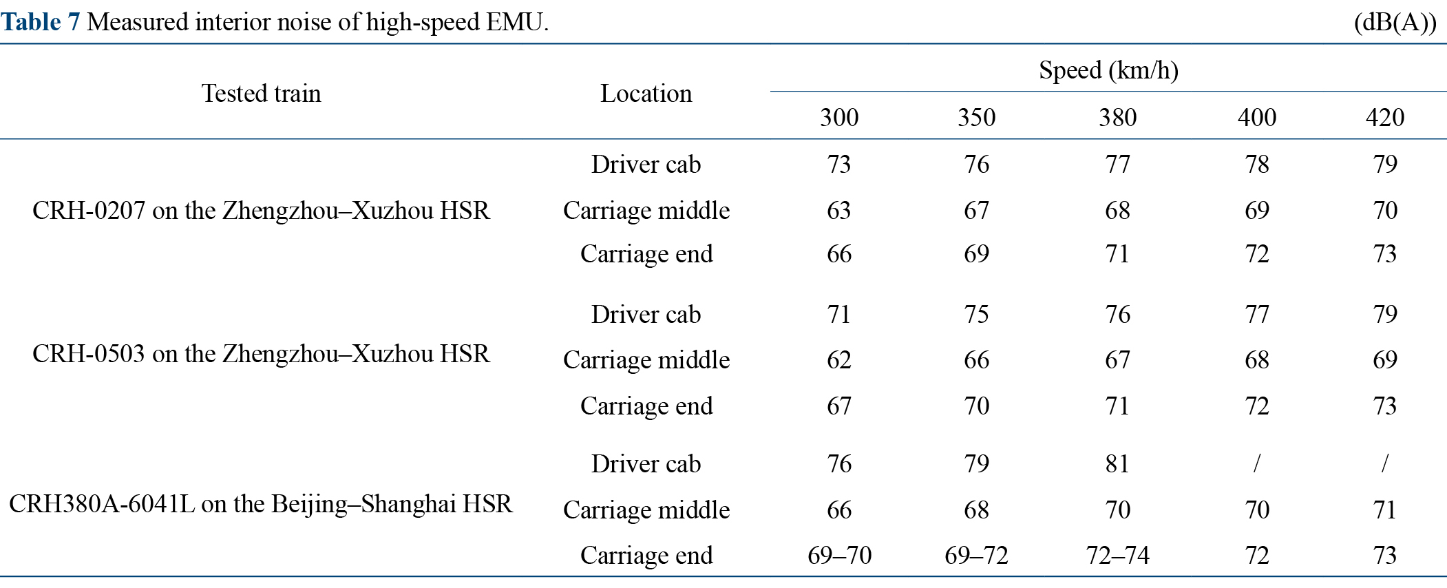
As can be seen from Table 6, the existing European codes lack provisions for speed levels over 350 km/h, while China has established a relatively complete noise evaluation standard system for speed levels of 350 km/h and above and the specified limits are also more stringent. To achive higher operation speed, China has carried out several interior noise test experiments on HSR EMUs, up to the speed of 420 km/h. The measured data are shown in Table 7.
It can be seen from Table 7 that the noise in the train increases with higher operating speeds, but remains within the limit at speeds of 350 km/h. This indicates that the interior noise levels of China's HSR are maintained within a relatively comfortable range for passengers
Noise control of high-speed railways is a systematic project that requires comprehensive management of noise. Based on targeted control of noise sources, the application of new infrastructure noise reduction technology should be promoted. Noise reduction of the wheel-rail system should be strengthened; more attention should be paid to the influence of track conditions on the radiated noise. Track acoustic control indicators should be formulated based on big data analysis of joint commissioning and dynamic acceptance of HSR, ensuring that the noise of EMU is controlled within a reasonable level throughout the whole life cycle. When developing higher speed HSR, it is necessary to consider strengthening the control of aerodynamic noises on the top of the EMU pantograph and diffracted sound on the top of the sound barrier to reduce the impact of railway noise emission.
In the process of unsteady operations such as starting, running, and braking, the force on the vehicle changes sharply, resulting in abrupt longitudinal movement between different units [27–29]. Under the action of longitudinal impulse, passengers will fall forward or backward due to inertial force, resulting in instability in standing and affecting the riding comfort and passenger safety.
In the process of train operation, multiple time-varying forces act simultaneously, and they interact and affect each other. When the train is in unsteady motion, the resistance, line resistance, traction force, dynamic braking force, braking force, and the interaction between train units produce "rigid impact", which create impulses.
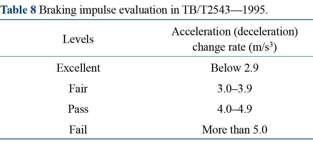
Train deceleration and the rate of deceleration are important indicators to measure the longitudinal impulse in passenger trains. On average, deceleration that is lower than 1.0 m/s2 is considered good performance, and the allowable deceleration value is 3.0 m/s2. The riding comfort decreases significantly if deceleration reaches 5.0 m/s2. The braking impulse is the change in the rate of acceleration (deceleration). The regulations on the braking impulse stipulated in TB/T2543—1995 are shown in Table 8.
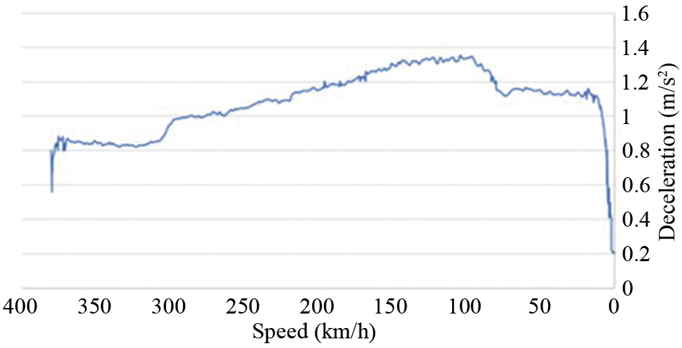
In the design of the EMU braking system in China, flexible control with a time constant is adopted for the control of braking force for both air braking and air-electric composite braking. Use CRH380BL as an example, the maximum emergency braking deceleration is lower than 1.4 m/s2 under the most unfavorable working condition ensuring ride comfort during braking. The decelerating curve of CRH380BL EMU is shown in Fig. 8. As seen in Fig. 8, the deceleration of CRH380BL is always below the limit, which ensures ride comfort.
The longitudinal impulse can be reduced from the following aspects: (1) Optimize the performance of the braking system. The braking system should have a high braking and release wave speed, good characteristics of pressure rise and release of the brake cylinder, and excellent emergency braking performance. (2) Adopt small gap coupler or tight coupler with elastic mastic buffer. Reducing the longitudinal gap of the coupler system is one of the most effective measures to reduce the longitudinal impulse. The tight coupler with elastic mastic buffer can significantly improve the longitudinal dynamic performance.
When the train passes through a curve, it tends to move outward under the action of centrifugal force, that is, curve centrifugal force [30–32]. When the centrifugal force is too great, passengers also tend to lean outward and may even fall, thus affecting their riding comfort.
To offset the inertial centrifugal force, the outer rail of the curve is raised appropriately. The gravity that acts on the train will produce a centripetal horizontal component, so that uniform stress and identical vertical wear and tear of the inner and outer rails can be achieved, which can also ensure the riding comfort of passengers. The superelevation of outer rail refers to difference in the horizontal height between the top surfaces of the outer and inner rail.
When a train travels along a curve at an equilibrium speed VP, the resulting force of the transverse component that is parallel to the rail top surface and the gravity falls on the centerline of the railway line. At this point, the vertical forces exerted on the rails by the inner and outer wheels are equal, and the track is under the most favorable stress condition in both lateral and vertical directions.
When the train's speed exceeds the equilibrium speed, the train is in a state of "insufficient superelevation", which results in an unbalanced centrifugal force and thus centrifugal acceleration. Centrifugal acceleration is related to the driving speed, the curve radius and the actual rail superelevation. If the train passes through the curve at a constant speed and in a steadystate, throughout the whole circular curve, its value remains constant, which is equivalent to a static lateral force acting on the vehicle body. Hence, this lateral force is called the quasi-static lateral force, and its corresponding acceleration is called quasi-static lateral acceleration. The quasi-static lateral force acting on the train body increases the lateral load between the wheel and rail, which leads to an uneven distribution of vertical load on the inner and outer rails, intensifies the load and stresses of each track component, and accelerates the deformation of track structure components. The quasi-static lateral acceleration acting on the train body can cause passengers to feel uncomfortable.
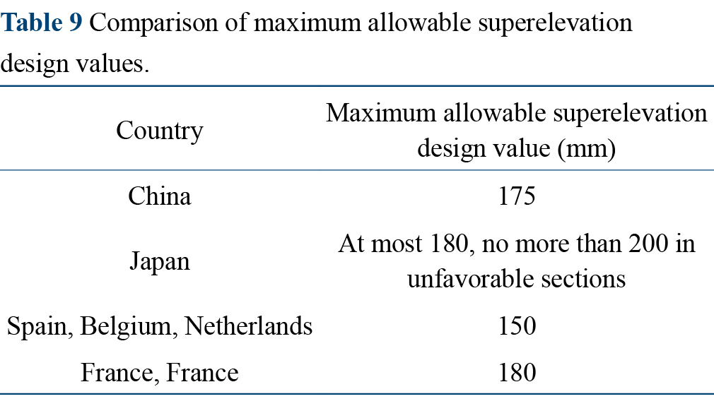
The factors that quantify the influence of centrifugal force on ride comfort are outer rail superelevation and insufficient superelevation values. When the train stops on a curve with superelevation of 200 mm or above, passengers will feel unstable, difficult to walk, and even dizzy. The maximum superelevation of HSRs abroad is generally 170–200 mm. China's HSR Design Code stipulates that the maximum allowable design value of superelevation is 175 mm. The maximum allowable design value of superelevation of different standards is compared in Table 9 below. It can be seen that the allowable design value of superelevation in China is higher.
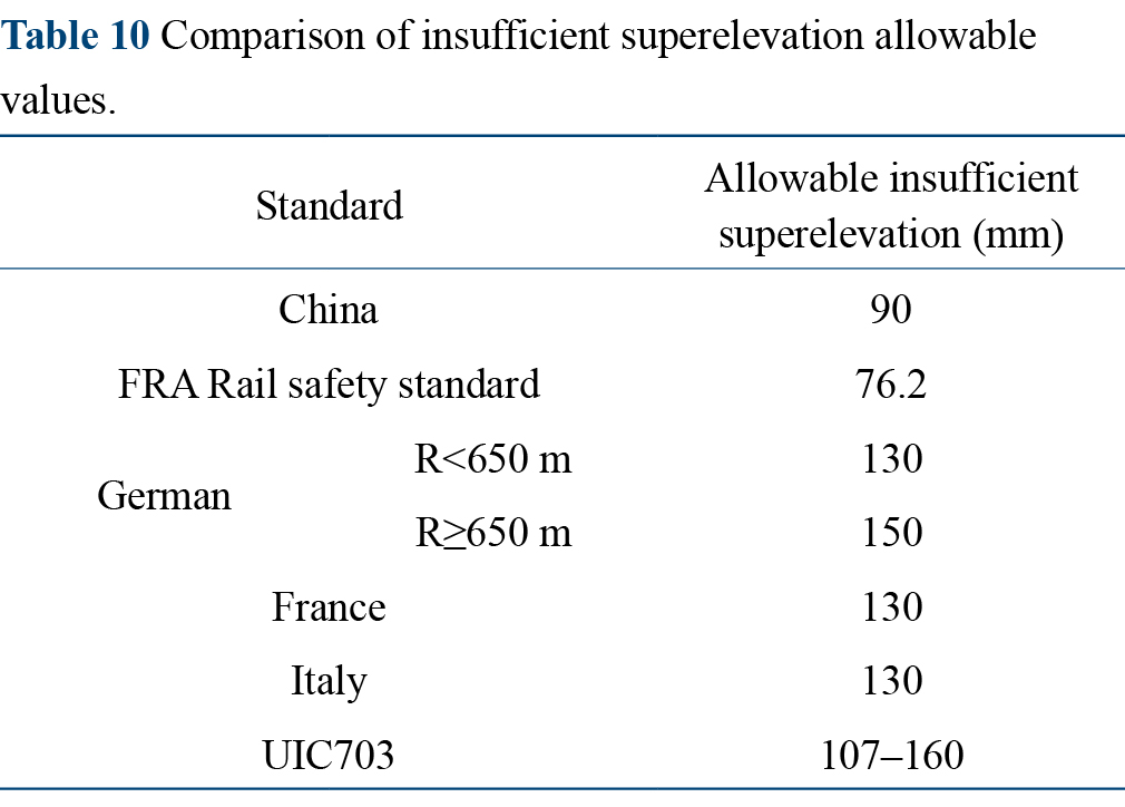
Once the track superelevation of the outer rail is set, it will become a fixed facility. However, the speed of different rolling stock passing through the curve is different, resulting in different centrifugal forces. The centrifugal force can be greater than the centripetal force provided by the superelevation when the train is running at a very high speed, which leads to insufficient superelevation. When the train speed is low and the centrifugal force is less than the centripetal force provided by the superelevation, excessive superelevation will be generated. A large insufficient superelevation value will cause discomfort, and excessive superelevation will crush the inner rail. The allowable values of insufficient superelevation of different standards are compared in Table 10.
In the speed-raising design of existing railway lines and the design of new HSR lines in China, the allowable curve insufficient superelevation value should neither follow the existing standards nor the standards of HSR specifications abroad. Instead, depending on the different power car and trailer car unit types, curve radius, and speed sections, different curve insufficient superelevation values, and speed restrictions should be stipulated and adopted.
This paper analyzed six significant indexes that influence the ride comfort of rolling stock, such as running stability, interior transient pressure, interior electromagnetic environment, interior noise, braking and longitudinal impulse, and curve centrifugal force. By comparing the evaluation methods and evaluation indexes of major countries in the world, it is found that comfort requirements for China's HSR are high. The threshold of each index is at the strictest level in the world. of several measured data have proven the excellent comfort level of China's HSR trains. To maintain the leading position of China's HSR technology in the world, innovative researches on fundamental theories still need to be carried out, simulation experiment needs to be conducted, as well as promoting the real-world application of academic achievements.
M. Peixer, P. Montenegro, H. Carvalho, D. Ribeiro, T. Bittencourt, and R. Calçada, "Running safety evaluation of a train moving over a high-speed railway viaduct under different track conditions," Engineering Failure Analysis, vol. 121, p. 105133, 2021.
X.-M. Shao, J. Wan, D.-W. Chen, and H.-B. Xiong, "Aerodynamic modeling and stability analysis of a high-speed train under strong rain and crosswind conditions," Journal of Zhejiang University-SCIENCE A, vol. 12, pp. 964–970, 2011.
J.-H. Lee, C.-Y. Lee, J.-M. Jo, J. Lim, J. Choe, Y. Sun, et al., "Analysis of the influence of magnetic stiffness on running stability in a high-speed train propelled by a superconducting linear synchronous motor," Proceedings of the Institution of Mechanical Engineers, Part F: Journal of Rail and Rapid Transit, vol. 233, pp. 170–186, 2019.
W. Zhai, P. Liu, J. Lin, and K. Wang, "Experimental investigation on vibration behaviour of a CRH train at speed of 350 km/h," International Journal of Rail Transportation, vol. 3, pp. 1–16, 2015.
C. Liu, D. Thompson, M. J. Griffin, and M. Entezami, "Effect of train speed and track geometry on the ride comfort in high-speed railways based on ISO 2631-1," Proceedings of the Institution of Mechanical Engineers, Part F: Journal of Rail and Rapid Transit, vol. 234, pp. 765–778, 2020.
L. Zuo and S. Nayfeh, "Low order continuous-time filters for approximation of the ISO 2631-1 human vibration sensitivity weightings," Journal of sound and vibration, vol. 265, pp. 459–465, 2003.
A. R. Andrade and P. F. Teixeira, "A Bayesian model to assess rail track geometry degradation through its life-cycle," Research in Transportation Economics, vol. 36, pp. 1–8, 2012.
EN 14363: 2016Railway Applications—Testing and Simulation for the Acceptance of Running Characteristics of Railway Vehicles-Running Behavior and Stationary Tests. British Standards Institute. 2016.
Y. Jiang, B. K. Chen, and C. Thompson, "A comparison study of ride comfort indices between Sperling's method and EN 12299," International Journal of Rail Transportation. vol. 7, pp. 279–296, 2019.
B. Kufver, R. Persson, and J. Wingren, "Certain aspects of the CEN standard for the evaluation of ride comfort for rail passengers," WIT Transactions on The Built Environment, vol. 114, pp. 605–614, 2010.
J. A. Zakeri, M. M. Feizi, M. Shadfar, and M. Naeimi, "Sensitivity analysis on dynamic response of railway vehicle and ride index over curved bridges," Proceedings of the Institution of Mechanical Engineers, Part K: Journal of Multi-Body Dynamics, vol. 231, pp. 266–277, 2017.
C. Deng, J. Zhou, D. Thompson, D. Gong, W. Sun, and Y. Sun, "Analysis of the consistency of the Sperling index for rail vehicles based on different algorithms," Vehicle System Dynamics, vol. 59, pp. 313–330, 2021.
X.-F. Liang, G. Chen, X.-B. Li, and D. Zhou, "Numerical simulation of pressure transients caused by high-speed train passage through a railway station," Building and Environment, vol. 184, p. 107228, 2020.
L. Zhang, M.-Z. Yang, J.-Q. Niu, X.-F. Liang, and J. Zhang, "Moving model tests on transient pressure and micro-pressure wave distribution induced by train passing through tunnel," Journal of Wind Engineering and Industrial Aerodynamics, vol. 191, pp. 1–21, 2019.
W. Yang, E. Deng, M. Lei, Z. Zhu, and P. Zhang, "Transient aerodynamic performance of high-speed trains when passing through two windproof facilities under crosswinds: A comparative study," Engineering Structures, vol. 188, pp. 729–744, 2019.
J. Niu, Y. Sui, Q. Yu, X. Cao, and Y. Yuan. "Aerodynamics of railway train/tunnel system: A review of recent research," Energy and Built Environment, vol. 1, pp. 351–375, 2020.
T. Liu, M. Chen, X. Chen, S. Geng, Z. Jiang, and S. Krajnović, "Field test measurement of the dynamic tightness performance of high-speed trains and study on its influencing factors," Measurement, vol. 138, pp. 602–613, 2019.
A. Knight-Percival, C. Johnson, B. Richards, S. Palmer, and N. Bowring, "Mapping of the electromagnetic environment on the railway: Condition monitoring of signalling assets," Proceedings of the Institution of Mechanical Engineers, Part F: Journal of Rail and Rapid Transit, vol. 234, pp. 246–256, 2020.
R. Armstrong, L. Dawson, A. Rowell, C. Marshman, and A. Ruddle, "The effect of fully electric vehicles on the low frequency electromagnetic environment,"2015 IEEE International Symposium on Electromagnetic Compatibility (EMC), Taipei, China, 2015, pp. 662–667.
Y. Wen and W. Hou, "Research on electromagnetic compatibility of Chinese high speed railway system," Chinese Journal of Electronics, vol. 29, pp. 16–21, 2020.
Protection ICoN-IR, "Guidelines for limiting exposure to electromagnetic fields (100 kHz to 300 GHz)," Health physics. vol. 118, pp. 483–524, 2020.
A. Cozza and B. Démoulin, "On the modeling of electric railway lines for the assessment of infrastructure impact in radiated emission tests of rolling stock," IEEE Transactions on Electromagnetic Compatibility, vol. 50, pp. 566–576, 2008.
L. Xiaotian, Z. Haijing, Q. Bo, and H. Bochong, "EMC in rail transportation," Energy Procedia, vol. 104, pp. 526–531, 2016.
Y. Soeta and R. Shimokura, "Survey of interior noise characteristics in various types of trains," Applied Acoustics, vol. 74, pp. 1160–1166, 2013.
K. Qian, Z. Hou, Q. Sun, Y. Gao, D. Sun, and R. Liu, "Evaluation and optimization of sound quality in high-speed trains," Applied Acoustics, vol. 174, p. 107830, 2021.
Y. J. Jang, J. D. Chung, and J.-C. Lee, "Analysis and investigation of international (UIC, EN, IEC) and domestic standards (test methods) for climatic wind tunnel test of rolling stock," Journal of the Korea Academia-Industrial Cooperation Society, vol. 21, pp. 782–789, 2020.
M. Y. Yu, X. Sun, and J. B. Lin, "Analyses to mechanism of train longitudinal impulse,"Fourth International Heavy Haul Railway Conference, Brisbane, Australia, 1989, pp. 591–594.
Q. Wu, M. Spiryagin, and C. Cole, "Longitudinal train dynamics: An overview," Vehicle System Dynamics, vol. 54, pp. 1688–1714, 2016.
C. Cole, M. Spiryagin, and C. Bosomworth, "Examining longitudinal train dynamics in ore car tipplers," Vehicle System Dynamics, vol. 55, pp. 534–551, 2017.
K. Zboiński, "Dynamical investigation of railway vehicles on a curved track," European Journal of Mechanics-A/Solids, vol. 17, pp. 1001–1020, 1998.
D. Zhang, Y. Tang, D. B. Clarke, Q. Peng, and C. Dong, "An innovative method for calculating diagonal lashing force of cargo on railway wagons in a curve alignment," Vehicle System Dynamics, vol. 59, pp. 352–374, 2021.
 Top
Top